Removable coin bin

Inactive Publication Date: 2005-03-31
CUMMINS-ALLISON CORP
View PDF22 Cites 43 Cited by
  • Summary
  • Abstract
  • Description
  • Claims
  • Application Information

AI Technical Summary

Benefits of technology

[0013] In another aspect of the current invention, a removable coins storage apparatus is used in a coin processing device, and includes a removable bin, a handle, and a brake. The removable bin includes a first opening to allow the placement of coins inside the removable bin, and a second opening to allow the coins to be discharged from the removable bin. The handle is pivotally coupled to the removable bin for transporting the removable bin, wherein the han

Problems solved by technology

One problem that exists in some prior art devices is that manual intervention is required to remove the coins from the storage device, wherein an operator physically removes small amounts of coins at a time until the entire amount of coins has been removed.
Aside from being time consuming, the manual intervention is also susceptible to the loss of coins, either through the operator losing or stealing coins.
Another problem that exists in some prior art devices is that transportation of a storage device is extremely difficult.
Because some of these storage devices can weigh hundreds of pounds, such as around 500 pounds, it might take more than one person to lift and transport a storage device.
The transportation difficulty becomes even more troublesome if the storage device is located in a hard-to-get position, such as in a container designed to tightly enclose the storage device.
Unless the storage device is designed for allowing a single person to easily transport the heavy load, the process of transporting such a storage device can become unduly cumbersome, if not nearly, impossible.
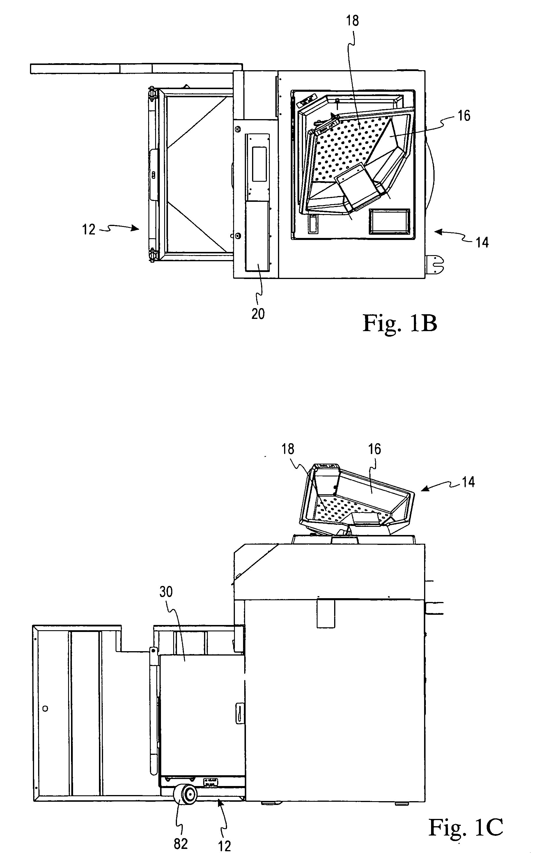
Similarly, some prior art devices are inadequate because they are not specifically designed to facilitate transportation by using commercially available transportation machines, such as a hand-operated truck, a motorized truck, or a forklift.
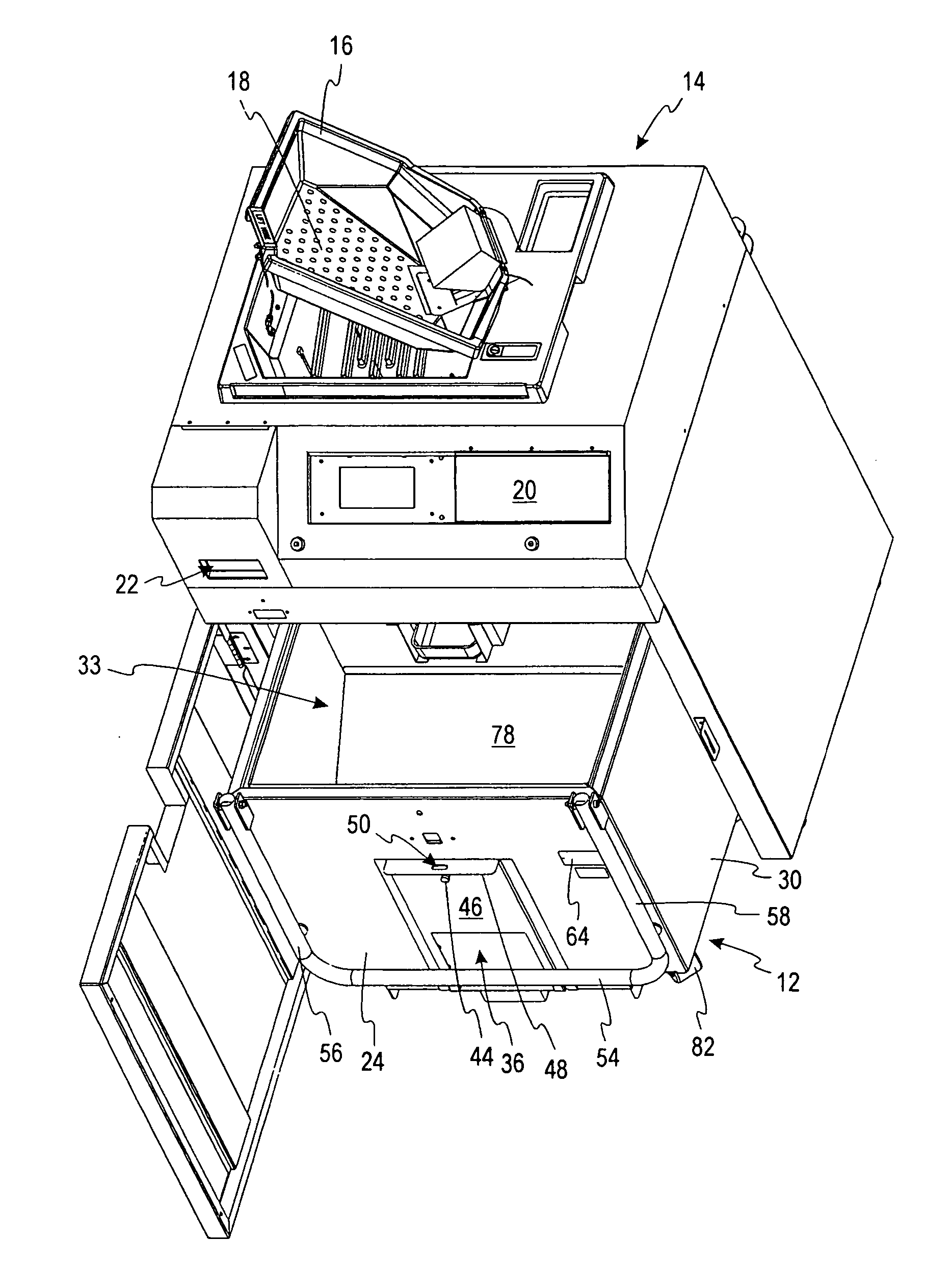
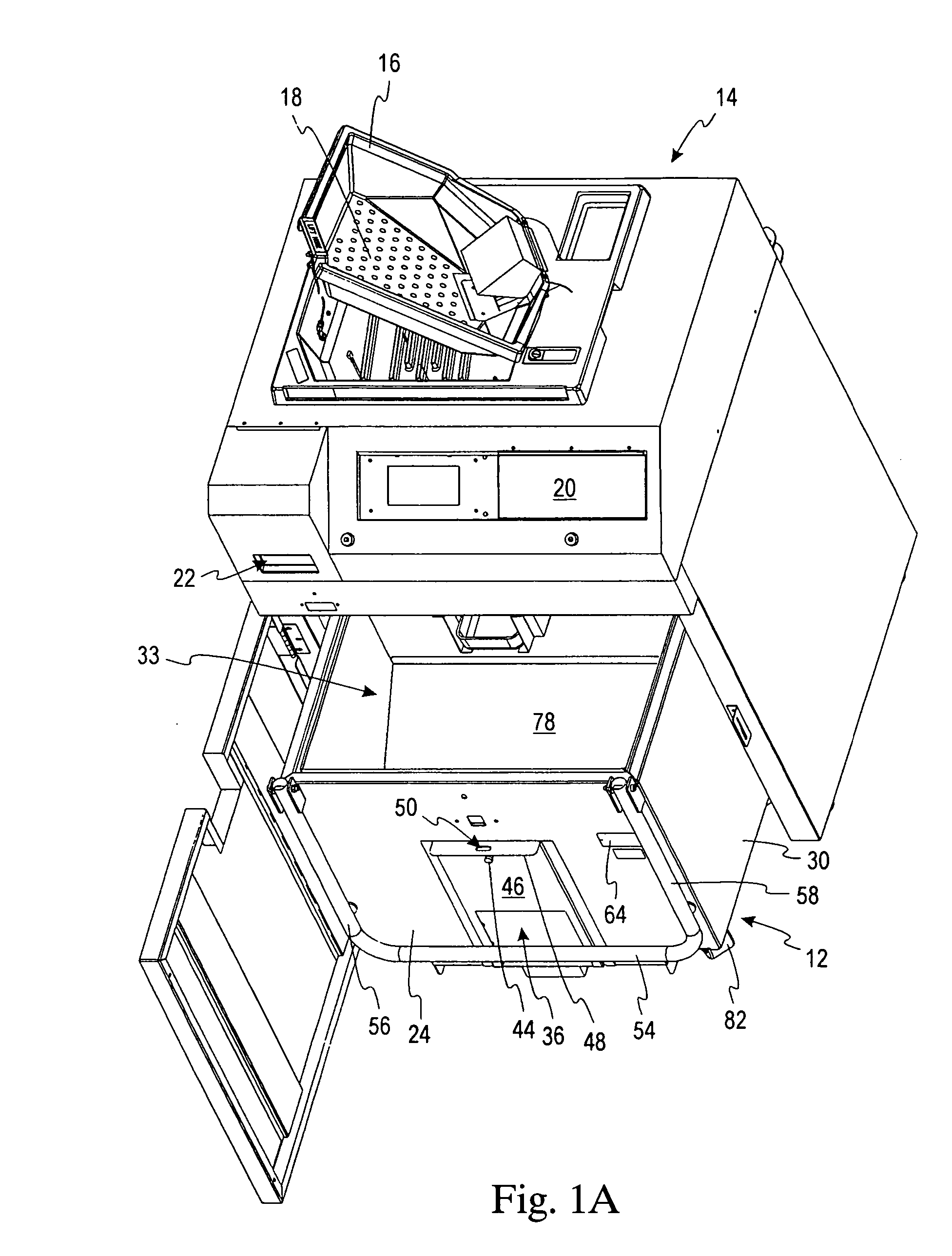
One other problem experienced during transportation of coins is that a removable coin bin can become unstable when the bin is empty.
For example, an emp

Method used


Image

  • Removable coin bin
  • Removable coin bin
  • Removable coin bin

Examples


Example

[0034] While the invention is susceptible to various modifications and alternative forms, specific embodiments are shown by way of example in the drawings and are described in detail herein. It should be understood, however, that the invention is not intended to be limited to the particular forms disclosed. Rather, the invention is to cover all modifications, equivalents, and alternatives falling within the spirit and scope of the invention as defined by the appended claims.

DETAILED DESCRIPTION OF THE ILLUSTRATED EMBODIMENT

[0035] Referring now to the drawings, and initially to FIGS. 1a-1c, a removable coin bin 12, i.e., a removable coin storage apparatus, according to the present invention is shown in usage with a coin processing device or machine 14. A detailed description of the coin bin 12 will be provided after a brief description of the coin machine 14. Note that the term coin machine 14 includes such machines as a coin redemption machine, automatic teller machine (ATM), coin...


PUM


Abstract

A removable coin storage apparatus is used in a coin processing device, and includes a removable bin for storing and transporting coins. The removable bin has a stopped position and a moving position. The coin storage apparatus further includes a brake device that is pivotally coupled to the removable bin for preventing movement of the removable bin in the stopped position. The brake device has a manually moveable element that is movable between a first position and a second position, each one of the first position and the second position corresponding to one of the stopped position and the moving position of the removable bin. The brake device also has a contact surface for exerting a frictional force on a floor surface in the stopped position of the removable bin.

Description

CROSS-REFERENCE TO RELATED APPLICATIONS [0001] This application is a continuation-in-part of U.S. patent application Ser. No. 10 / 251,211, filed Sep. 20, 2002, which is incorporated herein by reference in its entirety.FIELD OF THE INVENTION [0002] This invention is directed generally to coin handling devices and, more specifically, to a removable coin bin for use in a coin redemption machine. BACKGROUND OF THE INVENTION [0003] Coin storage devices are widely used in a variety of coin processing machines, such as coin redemption machines, automated teller machines (ATMs), vending machines, gaming machines, and toll booth machines. Regardless of whether these coin processing machines are designed to perform one function, such as counting a number of coins, or several functions, such as counting, sorting, and identifying the coins, all coin processing machines usually require a convenient device for storing the coins after they have been processed. Some examples of such storage devices ...

Claims


Application Information

Patent Timeline
IPC IPC(8): G07F9/06
CPCG07F9/06
Inventor BOCHONOK, STEVE T.BLAKE, JOHN R.
Owner CUMMINS-ALLISON CORP
Why Eureka
Try Eureka