
Ink cartridge and ink-jet printer

a technology of inkjet printers and ink cartridges, applied in printing and other directions, can solve the problems of inability to meet the requirements of printing,

Active Publication Date: 2005-03-31
BROTHER KOGYO KK
View PDF7 Cites 82 Cited by
  • Summary
  • Abstract
  • Description
  • Claims
  • Application Information

AI Technical Summary

Benefits of technology

Accordingly, a principal object of the present invention is to provide an ink cartridge which makes it possible to indicate the amount of the ink contained in the ink cartridge without being excessively effected by the disturbance such as the surface tension of the ink, and an ink-jet printer which includes the same.
In the ink-jet printer of the present invention, the detector (21) may be a light-transmissive type sensor. Accordingly, it is possible to use the cheap light-transmissive type sensor. Therefore, it is possible to realize the low cost of the ink-jet printer.

Problems solved by technology

However, any error tends to arise in such calculation.
As a result, the ink is wasted.
As described above, the technique suggested by Japanese Patent Application Laid-open No. 9-001819 tends to suffer from the influence of the disturbance such as the surface tension of the ink.
Therefore, a problem arises such that it is impossible to indicate any correct amount of the ink contained in the ink cartridge.

Method used


Image

  • Ink cartridge and ink-jet printer
  • Ink cartridge and ink-jet printer
  • Ink cartridge and ink-jet printer

Examples


first embodiment

A first embodiment according to the present invention will be explained with reference to the drawings.

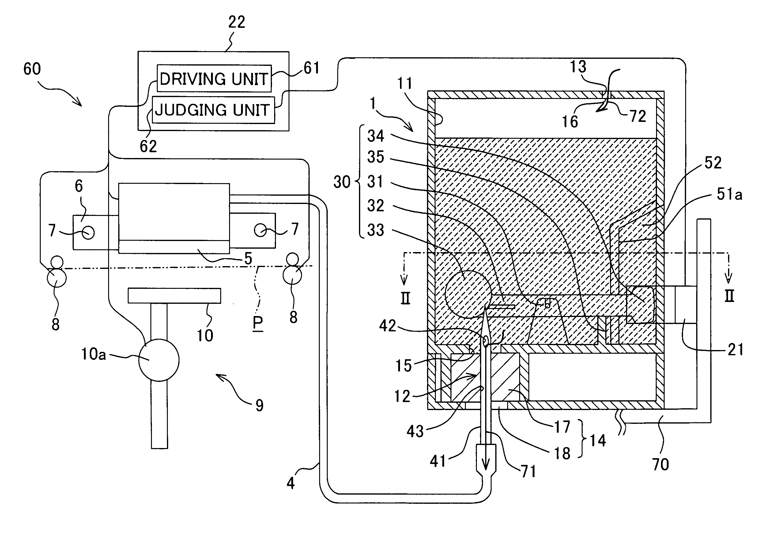
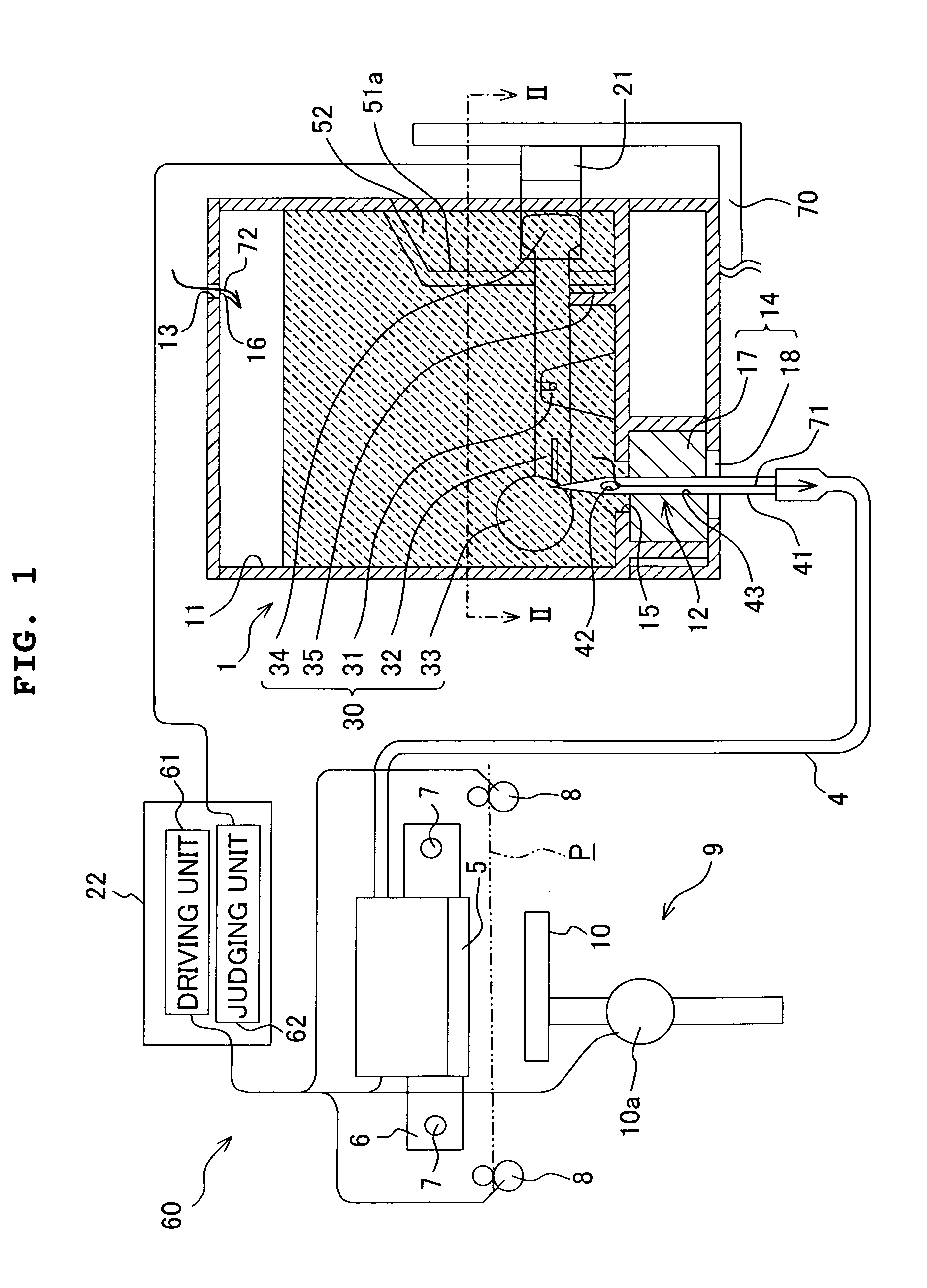
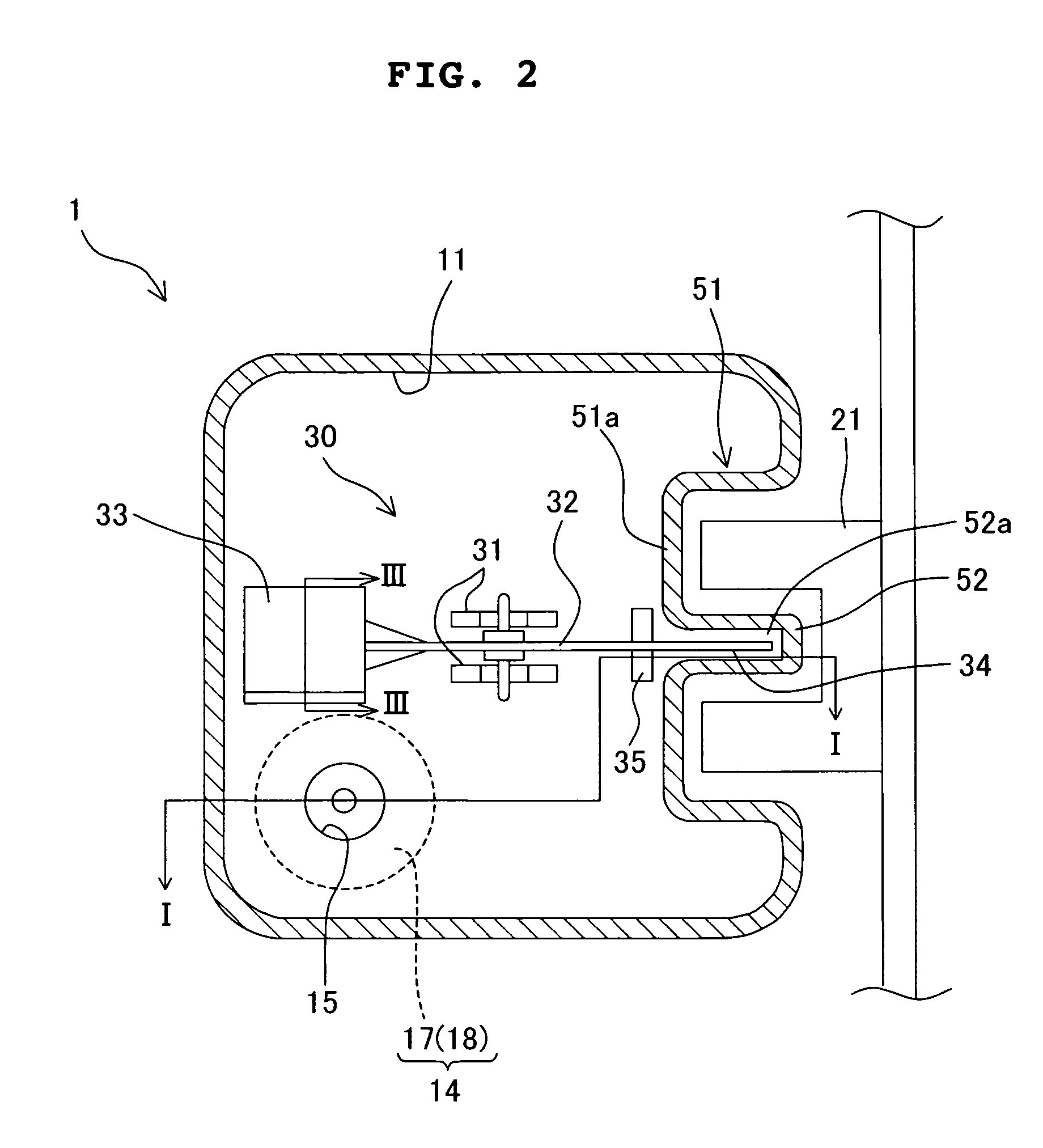
FIG. 1 shows a partial schematic view illustrating an ink-jet printer including an ink cartridge according to the first embodiment. The ink cartridge 1 shown in FIG. 1 illustrates a cross-sectional structure of the ink cartridge 1 as being cut along a line I-I shown in FIG. 2. An arrow 71 shown in FIG. 1 indicates the flow of the ink, and an arrow 72 indicates the flow of the atmospheric air. FIG. 2 shows a sectional view illustrating the ink cartridge 1 taken along a line II-II shown in FIG. 1. FIG. 3 shows a sectional view illustrating a float 33 taken along a line III-III shown in FIG. 2.

As shown in FIG. 1, the ink-jet printer 60 includes an ink-jet head 5 which discharges the light-transmissive ink toward the recording paper P, an ink cartridge 1 which stores the ink (I in the drawing) to be discharged to the ink-jet head 5, a carriage 6 which linearly reciprocates and move...

second embodiment

Next, a second embodiment according to the present invention will be explained with reference to the drawings. In the second embodiment, only the shutter mechanism differs from that in the first embodiment. Therefore, in the drawings concerning the second embodiment, the same members as those of the first embodiment are designated by the same reference numerals, any explanation of which will be omitted.

FIG. 7 shows sectional views illustrating an ink cartridge according to the second embodiment. FIG. 7A shows a state in which the interior of the ink tank 11 is filled with the ink, and FIG. 7B shows a state in which the ink in the ink tank 11 is consumed. FIG. 8 shows a sectional view taken along a line VIII-VIII shown in FIG. 7B. The shutter mechanism 30A of the ink cartridge 1A is driven on the basis of the amount of the ink stored in the ink tank 11. As shown in FIG. 7A, the shutter mechanism 30A is arranged at the bottom of the ink tank 11. The shutter mechanism 30A includes a ...

third embodiment

A third embodiment of the present invention will be explained. In the third embodiment, the present invention is applied to an ink-jet printer capable of discharging four color inks.

As shown in FIG. 11, the ink-jet printer 101 includes, for example, an ink-jet head 102 which is provided with nozzles 102a for discharging the four color inks of cyan (C), yellow (Y), magenta (M), and black (K) to the recording paper P, four holders 104 (104a, 104b, 104c, 104d) which serve as cartridge-installing sections for installing four ink cartridges 103 (103a, 103b, 103c, 103d) for storing the four color inks respectively, a carriage 105 which linearly reciprocates and moves the ink-jet head 102 along a guide 109 in a certain direction (direction perpendicular to the paper surface), a transport mechanism 106 which transports the recording paper P in the direction perpendicular to the direction of movement of the ink-jet head 102 in parallel to the ink discharge surface of the ink-jet head 102,...


PUM


Abstract

An ink cartridge has an ink tank in which the ink is stored, and a shutter mechanism which is arranged in the ink tank. The shutter mechanism includes a lever which is supported swingably and which has one end provided with a shutter and the other end provided with a float. The mass and the volume of the float are set so that the first direction, in which the lever moves by the buoyancy and the gravity generated when the entire shutter mechanism is positioned in the ink, is opposite to the second direction in which the lever moves by the buoyancy and the gravity when a part of the float protrudes from the ink liquid surface. A residual amount of an ink is indicated without being excessively affected by any disturbance such as the surface tension of the ink.

Description

BACKGROUND OF THE INVENTION 1. Field of the Invention The present invention relates to an ink cartridge which supplies an ink to an ink-jet head for performing printing by discharging the ink, and an ink-jet printer including the same. 2. Description of the Related Art An ink-jet printer is known, in which an ink is discharged from nozzles to recording paper to perform the printing. Such an ink-jet printer is generally provided with a detachable ink cartridge. When an ink-jet head is driven to perform the discharge operation in a state in which the ink is empty in the ink cartridge, then the printing is not only performed, but the air sometimes makes invasion into the ink-jet head. The ink-jet head, into which the air has made invasion, cannot be used in some cases. Therefore, it is necessary to detect the amount of the ink stored in the ink cartridge. A method for detecting the amount of the ink is conceived, in which the amount of the ink is detected by estimating and accumula...

Claims


Application Information

Patent Timeline
Patent Type & Authority Applications(United States)
IPC IPC(8): B41J2/175
CPCB41J2/17513B41J2/17523B41J2/17546B41J2002/17576B41J2/17553B41J2/17566B41J2002/17573B41J2/1755
Inventor KATAYAMA, NAOKISASAKI, TOYONORIKANBE, TOMOHIRO
Owner BROTHER KOGYO KK
Learn More