Exposure system and production method for exposure system

a production method and exposure system technology, applied in the field of exposure apparatus, can solve the problems of inability to make correct corrections, inability to correct, and inability to corr

Active Publication Date: 2005-03-31
CITIZEN WATCH CO LTD
View PDF7 Cites 14 Cited by
  • Summary
  • Abstract
  • Description
  • Claims
  • Application Information

AI Technical Summary

Benefits of technology

Accordingly, it is an object of the present invention to provide an exposure apparatus that can determine a correction value for each individual light-emitting part by employing a method that detects the amount of light corresponding to one particular light-emitting part from composite light containing light rays from adjacent light-emitting parts, and a production method for producing such an exposure apparatus.
It is another object of the present invention to provide an exposure apparatus that can determine a correction value for each individual light-emitting part by measuring the amount of light of each of the plurality of light-emitting parts in the exposure head under the same conditions without causing changes in the environmental conditions of the light-emitting parts and the light sensor, and a production method for producing such an exposure apparatus.
It is a further object of the present invention to provide an exposure apparatus that can correct the amount of light of each of the plurality of light-emitting parts in the exposure head in such a manner as not to cause nonuniformity in exposure due to light from adjacent light-emitting parts, and a production method for producing such an exposure apparatus.
To achieve the above objects, there is provided, according to the present invention, a production method comprising the steps of lighting the plurality of light-emitting parts at the same time, detecting an output light-amount distribution across all of the plurality of light-emitting parts by making measurements using a line-like light-receiving device, detecting a peak position corresponding to each of the light-emitting parts by using the output light-amount distribution, detecting the amount of light of each light-emitting part based on the peak position, and determining, based on the amount of light of each light-emitting part, a correction value for correcting nonuniformity in the amount of light of the light-emitting part. As the correction value for each individual light-emitting part can be determined by employing the method that detects the amount of light corresponding to one particular light-emitting part from composite light containing light rays from adjacent light-emitting parts, a correct shading correction can be accomplished.

Problems solved by technology

With the first prior art method described above, it has basically not been possible to make a correct correction.
With the second prior art method described above, while the correction can be made for the effects of adjacent light at the same time, there has been the problem that the correction takes too much time and labor since it takes the steps of exposure, development, and measurement.
Further, the third prior art method described above aims at correcting for the effects of adjacent light, but the method itself is wrong and a correct correction cannot be made.

Method used


Image

  • Exposure system and production method for exposure system
  • Exposure system and production method for exposure system
  • Exposure system and production method for exposure system

Examples


first embodiment

A first embodiment according to the present invention will be described below with reference to drawings.

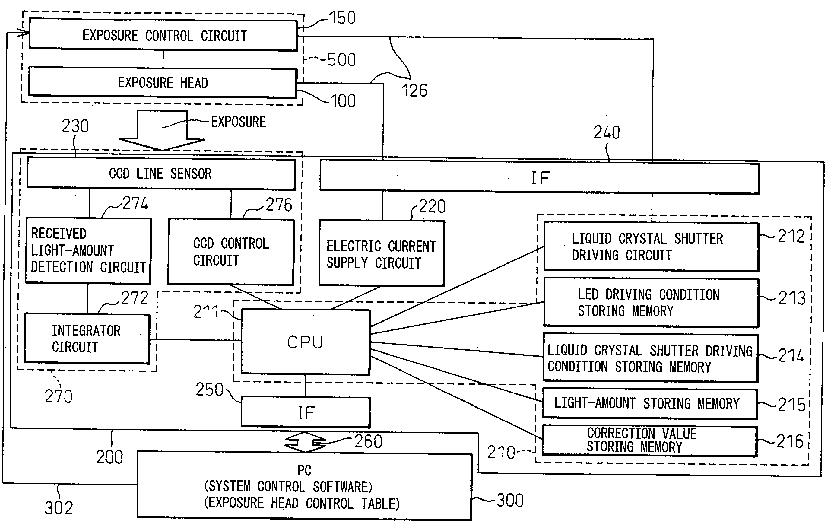
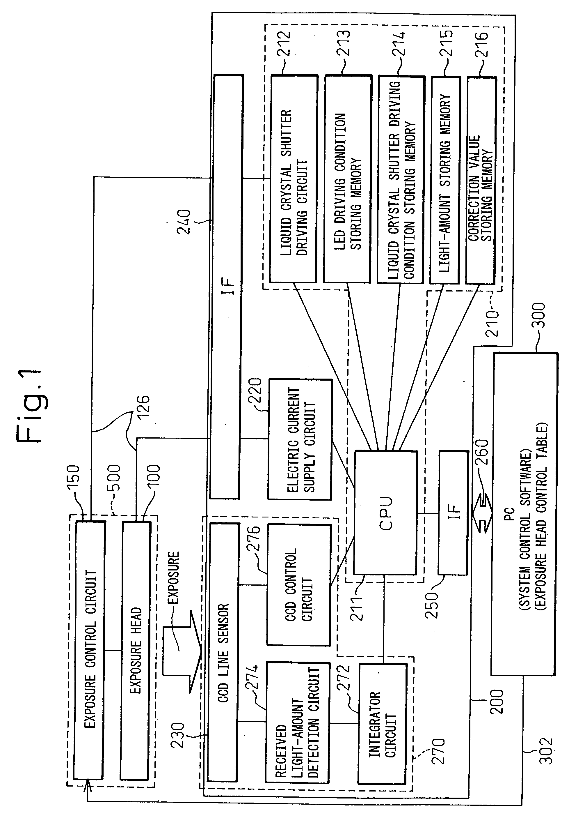
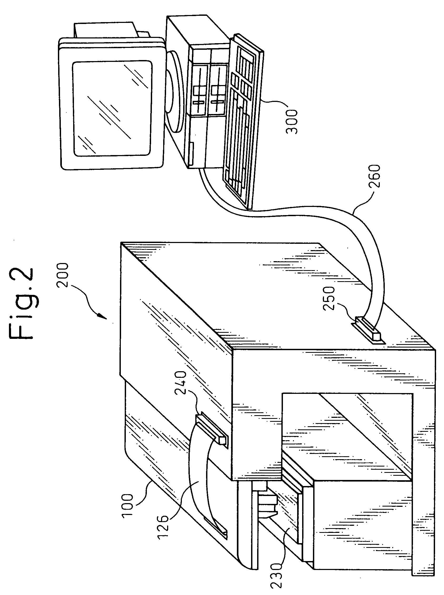
FIG. 1 is a diagram showing an overview of a production system, and FIG. 2 is a diagram for explaining an external view of the system.

As shown in FIGS. 1 and 2, the production system comprises an exposure head 100 to be measured, a measuring apparatus 200, and a personal computer (hereinafter referred to as the PC) 300 for performing control.

The exposure head 100 is mounted on the measuring apparatus 200 using an attachment not shown, and a signal line 126 is connected to an interface (hereinafter referred to as the IF) 240 of the measuring apparatus 200. The measuring apparatus 200 and the PC 300 are interconnected by a bus line 260 so that data can be transferred between them. Further, the exposure head 100 is connected to an exposure control circuit 150, which together constitute an exposure apparatus 500.

As shown in FIG. 1, the measuring apparatus 200 includes a driving...


PUM


Abstract

The invention is directed to the provision of an exposure apparatus that can determine a correction value for each individual light-emitting part by employing a method that detects the amount of light corresponding to one particular light-emitting part from composite light containing light rays from adjacent light-emitting parts, and also to the provision of a method for producing such an exposure apparatus. The production method according to the invention comprises the steps of lighting a plurality of light-emitting parts at the same time, detecting an output light-amount distribution across all of the plurality of light-emitting parts by making measurements using a line-like light-receiving device, detecting a peak position corresponding to each light-emitting part by using the output light-amount distribution; detecting the amount of light of each light-emitting part based on the peak position, and determining, based on the amount of light of each light-emitting part, the correction value for correcting nonuniformity in the amount of light of the light-emitting part.

Description

BACKGROUND ART The present invention relates to an exposure apparatus in which correction values are prestored, for correcting variations in the amount of light among a plurality of pixels contained in a light modulating device, and a method for producing such an exposure apparatus. DESCRIPTION OF THE PRIOR ART It is known to provide an optical printer which forms a color image by exposing a color photosensitive material or the like to light by using an exposure head equipped with a plurality of light-emitting parts. As such an exposure head has a plurality of light-emitting parts, there has been the problem that variations occur in the amount of light among the plurality of light-emitting parts, resulting in an inability of obtain an image of good quality. To address this problem, it has been practiced to apply shading correction (light-amount correction) by detecting the variations among the light-emitting parts. In a first prior art method of shading correction, the amount of ...

Claims


Application Information

Patent Timeline
Patent Type & Authority Applications(United States)
IPC IPC(8): B41J2/45G06K15/12
CPCB41J2/45G06K15/1261G06K15/1209
Inventor SHIOTA, AKIRAYASUNAGA, MAKOTOMASUBUCHI, SADAOIWAKO, AKINOBUYOKOYAMA, MASAFUMI
Owner CITIZEN WATCH CO LTD
Why Eureka
Try Eureka