
Lamp device for eliminating blind spot in automotive vehicle

a technology for automotive vehicles and blind spots, applied in the field of automotive vehicles, can solve the problems of increasing the probability of a safety issue to be roused, and achieve the effect of widening the driver's field of view

Inactive Publication Date: 2005-03-31
LEE SEUNG SIN
View PDF3 Cites 5 Cited by
  • Summary
  • Abstract
  • Description
  • Claims
  • Application Information

AI Technical Summary

Benefits of technology

[0006] Accordingly, the present invention has been made keeping in mind the above problems occurring in the prior art, and a primary object of the present invention is to provide a lamp device for eliminating a blind spot in an automotive vehicle, which has an illumination lamp pivotally mounted to a side panel of the vehicle to offer a view to the rear to thereby widen a driver's field of view and contribute to elimination of one or more blind spots that cannot be normally seen by the driver using ordinary rearview mirrors.
[0007] Another object of the present invention is to provide a lamp device for eliminating a blind spot in an automotive vehicle, wherein an illumination lamp capable of offering a view to the rear is combined with a turn signal lamp mounted to a front panel at a side of the vehicle so as to contribute to elimination of one or more blind spots.

Problems solved by technology

However, the conventional inside and outside rearview mirrors constructed as mentioned above are encountered with a problem in that, since there exist one or more blind spots which can not be viewed by a driver through the mirrors, such as a bottom portion of the vehicle and zones substantially positioned on the same planes as the mirrors, the probability of a safety issue to be roused is increased when parking or backing up the vehicle.

Method used


Image

  • Lamp device for eliminating blind spot in automotive vehicle
  • Lamp device for eliminating blind spot in automotive vehicle
  • Lamp device for eliminating blind spot in automotive vehicle

Examples


Embodiment Construction

[0017] Reference will now be made in greater detail to a preferred embodiment of the invention, an example of which is illustrated in the accompanying drawings. Wherever possible, the same reference numerals will be used throughout the drawings and the description to refer to the same or like parts.

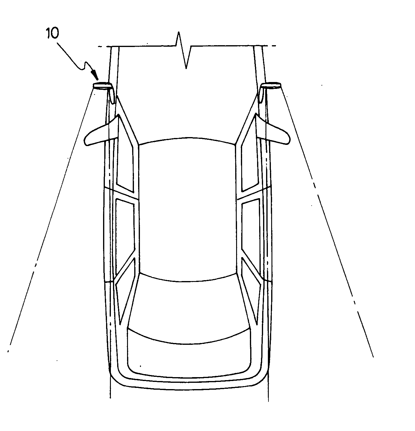
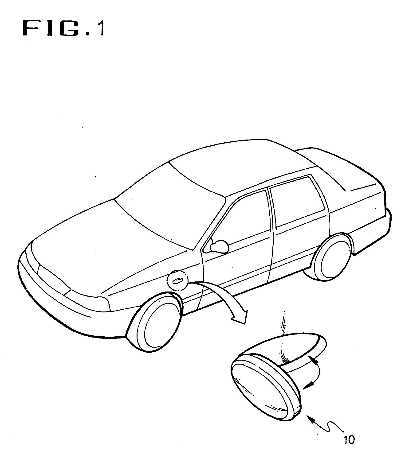
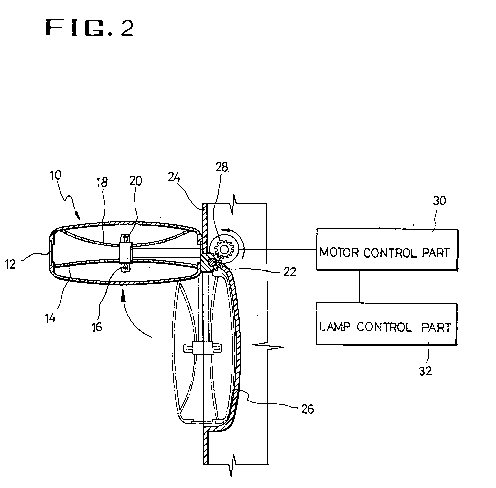
[0018]FIG. 1 is a partially enlarged schematic perspective view illustrating an automotive vehicle on which a lamp device for eliminating a dead spot in accordance with an embodiment of the present invention is installed; FIG. 2 is a diagrammatic cross-sectional view illustrating a construction of the lamp device for eliminating a blind spot according to the present invention, shown in FIG. 1; and FIG. 3 is a plan view illustrating an in-use state of the lamp device for eliminating a blind spot according to the present invention, shown in FIG. 1.

[0019] As shown in the drawings, a lamp device for eliminating a dead spot in accordance with an embodiment of the present invention comprises ...


PUM


Abstract

A lamp device for eliminating a blind spot in an automotive vehicle. A lamp member is received, at a predetermined location, in a side panel of a vehicle body. A drive member pivots the lamp member by a predetermined angle. A control member has a lamp control part for controlling the lamp member and a drive control part for controlling the drive member. The lamp member includes an illumination lamp controlled by a signal generated in the lamp control part, and a reflection mirror mounted to be positioned behind the illumination lamp. A turn signal lamp is combined to one surface of the lamp member. The lamp control part is actuated in a manner interlocked with operation of the drive member. The drive control part includes a driving motor for pivoting the lamp member by the predetermined angle, and a motor control portion for controlling the driving motor.

Description

BACKGROUND OF THE INVENTION [0001] 1. Field of the Invention [0002] The present invention relates, in general, to an automotive vehicle and, more particularly, to a lamp device for eliminating a blind spot in an automotive vehicle, which has an illumination lamp pivotally mounted to a side panel of the vehicle to offer a view to the rear to thereby widen a driver's field of view and contribute to elimination of one or more blind spots. [0003] 2. Description of the Prior Art [0004] As well known to those skilled in the art, mirrors installed on an automotive vehicle, such as an inside rearview mirror and an outside rearview mirror provided inside and outside the vehicle body, respectively, serve as provisions for securing a driver's rear view vision. That is to say, the inside rearview mirror is provided in a cabin of the vehicle to allow a driver to check an immediate rear field of view, and the outside rearview mirror is provided out of the cabin of the vehicle to allow the driver ...

Claims


Application Information

Patent Timeline
IPC IPC(8): B60Q1/22B60Q1/26B60Q1/36F21V33/00
CPCB60Q1/22B60Q1/36B60Q1/2665
Inventor LEE, SEUNG SIN
Owner LEE SEUNG SIN
Learn More