
Wireless infrastructure for broadcasting with return channel

a return channel and wireless infrastructure technology, applied in broadcast-related systems, transmissions, television systems, etc., can solve the problems of inability to provide broadband internet, limited satellite operators, and inability to provide return channels via satellite links

Inactive Publication Date: 2005-03-31
WI NETWORKS
View PDF22 Cites 74 Cited by
  • Summary
  • Abstract
  • Description
  • Claims
  • Application Information

AI Technical Summary

Problems solved by technology

Satellite operators however are limited in that it is impractical to provide a return channel via satellite link.
Nevertheless, if satellite providers wish to attract customers then they have to be able to compete with the packages offered by the cable companies.
Furthermore such a service cannot provide broadband Internet.
The disadvantage of this solution however is that LEO satellites require directional antennas and even for MEO the user's satellite dish has to be modified considerably or replaced in order to provide the necessary transmission power.
The solution is not economical, both the bandwidth and the necessary customer units are expensive.
Despite its popularity, there is slow deployment of broadband access (less than 20% coverage in the USA), mainly due to the limited coverage of xDSL capability and cable.
The success of WiFi (Wireless LAN) proves the demand of wireless access, but is limited to the short range so-called SOHO market.
Existing long-range wireless solutions, for example LMDS, MMDS, and the 3G (third generation cellular) are limited in functionality.
That is to say they currently suffer from the disadvantages of being asymmetric, and providing relatively low-speed data transfer.
Consequently they provide poor support for low-latency applications, although they are optimal for voice.
The services are relatively expensive to deploy and therefore currently almost non-existent.
The lack of an effective return channel and unicast support for DBS are a serious limitation on the growth and provisioning of new services—causing loss of market share and potential revenues from existing customers.
However the telephone return channel is paid for separately, is costly if used extensively and restricts availability of the user's telephone line.
Other solutions for return channel or unicast services support include satellite return (e.g. VSAT, ARTES) but the options are limited and the solutions are not economical.
Furthermore triple play is limited to multi channel television.

Method used


Image

  • Wireless infrastructure for broadcasting with return channel
  • Wireless infrastructure for broadcasting with return channel
  • Wireless infrastructure for broadcasting with return channel

Examples


Embodiment Construction

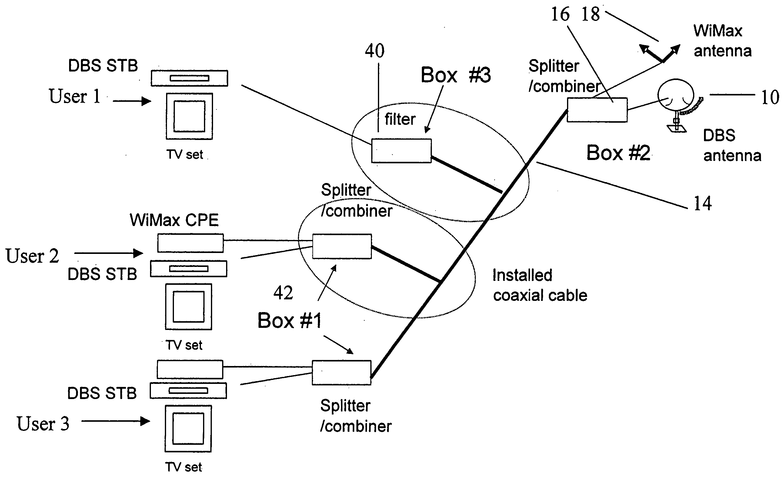
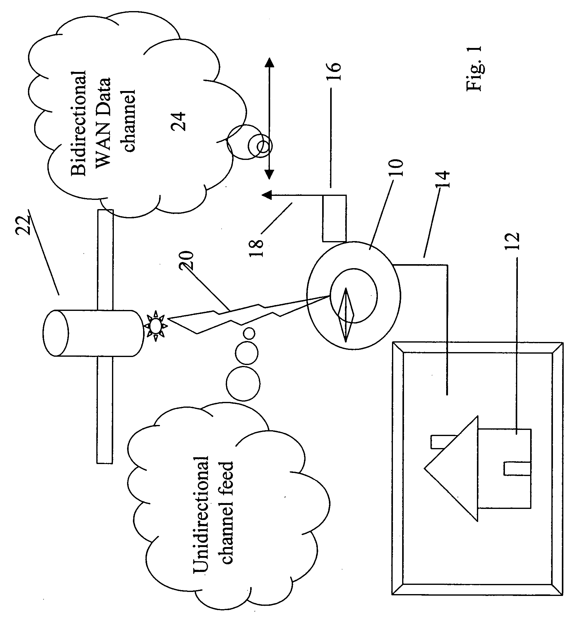
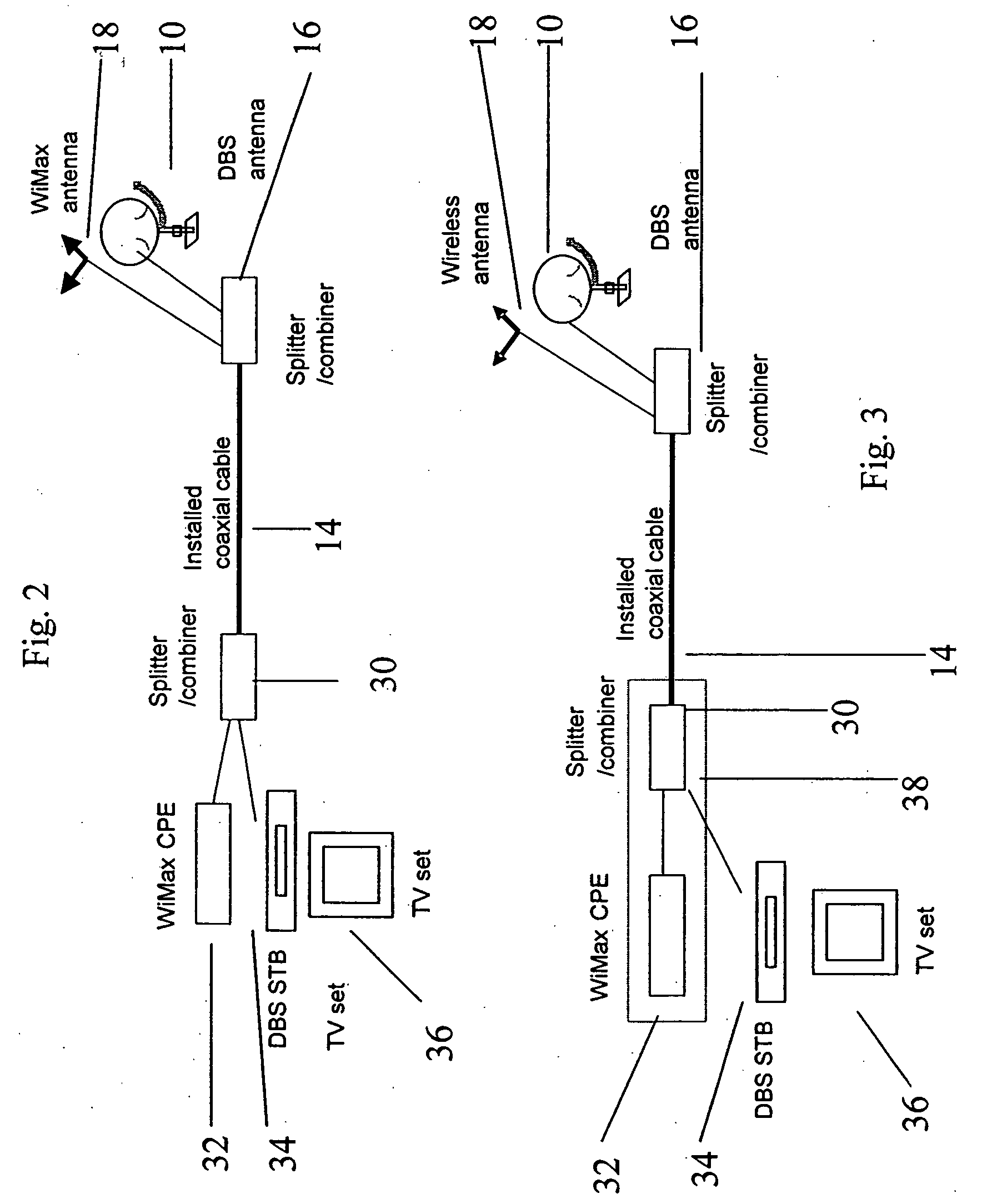
[0079] The present embodiments comprise a satellite (DVB-S) or terrestrial (DVB-T) based broadcasting system in which a digital TV feed is provided over a satellite or terrestrial connection to a user's receiver and wherein a 2-way preferably relatively high data rate channel is provided over a WAN which uses each receiver as a micro-base station for the WAN network. The WAN network may be mesh configured so that multiple paths exist for transmitting to each user, hence making it more robust. This may be best achieved simply by using the DBS install base. The WAN provides at least a return channel to enable interactive television and like services but may also provide an outward channel of high capacity allowing unicast. Thus services such as Internet, Internet telephony and video / gaming on demand can be made available.

[0080] It will be appreciated that whilst the present embodiments concentrated on DBS, or more precisely DVB-S (digital video broadcast via satellite) the invention ...


PUM


Abstract

Infrastructure for interactive broadcasting is provided using a wide area network for bi-directional transmission between a plurality of user nodes and a central source node, at least some of the user nodes comprising rooftop video broadcast receiving installations modified with a terrestrial bi-directional antenna and network transmission support electronics.

Description

RELATIONSHIP TO EXISTING APPLICATIONS [0001] The present application claims priority from U.S. Provisional Patent Application No. 60 / 501,411 filed Sep. 10, 2003 and U.S. Provisional Patent Application No. 60 / 515,441 filed Oct. 30, 2003.FIELD AND BACKGROUND OF THE INVENTION [0002] The present invention relates to wireless infrastructure to provide the return or interactive channel for broadcasting with a return channel, either via (DVB-S) or via (DVB-T) or in any other way, and, more particularly, but not exclusively to a method and apparatus for providing broadband services, interactive TV and gaming, broadband Internet access and internet telephony, full duplex, three-way communication and like services requiring at least a return channel to satellite or terrestrial television customers. Currently, cable operators are able to provide their customers with interactive television, Internet telephony and broadband Internet services. Satellite operators however are limited in that it is...

Claims


Application Information

Patent Timeline
IPC IPC(8): H04H40/90H04H60/95H04L12/28H04L12/56H04N7/10H04N7/173H04N7/20
CPCH04N21/472H04N21/2223H04N21/6143H04N21/6175H04N21/6181H04N2007/1739H04W84/12H04H40/90H04H60/95H04H2201/30H04N7/10H04N7/104H04N7/106H04N7/17309H04N7/20H04N21/6112
Inventor ATAD, EFRAIMHARPAK, OFEREFRON, EITAN
Owner WI NETWORKS
Learn More