
Transport stream recording/editing device and recording/editing method

a technology of recording/editing device and transport stream, which is applied in the direction of electronic editing digitized analogue information signal, instruments, television systems, etc., can solve the problems of difficulty in carrying out such editing operations, video packets and audio packets that are multiplexed into a ts are not always synchronized timewise, and the record capacity of a recording device must be larger than the capacity of the ts to be recorded

Inactive Publication Date: 2005-03-31
KK TOSHIBA
View PDF3 Cites 17 Cited by
  • Summary
  • Abstract
  • Description
  • Claims
  • Application Information

AI Technical Summary

Problems solved by technology

However, video packets and audio packets that are multiplexed into a TS are not always synchronized timewise on the stream.
Accordingly, it has been difficult to carry out such editing operations as designating a certain time area and deleting the range concerned.
Consequently, the record capacity of a recording device must be larger than the capacity of the TS to be recorded, which has been a problem with the prior art.
Consequently, devices become complicated, which has been another problem with the prior art.
Further, in the case where, editing is desired again after editing is carried out once and a TS is output, it is not easy to recover a portion deleted in previous editing for re-editing.

Method used


Image

  • Transport stream recording/editing device and recording/editing method
  • Transport stream recording/editing device and recording/editing method
  • Transport stream recording/editing device and recording/editing method

Examples


first embodiment

[0024] (First Embodiment)

[0025] Embodiments of the present invention will be illustrated in more details by reference to the accompanying drawings.

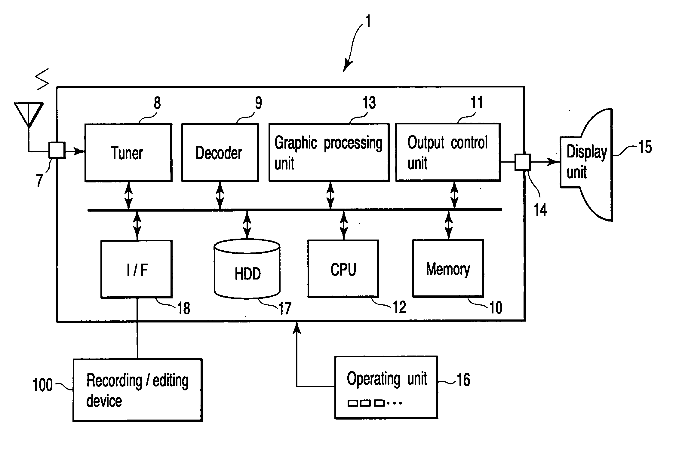
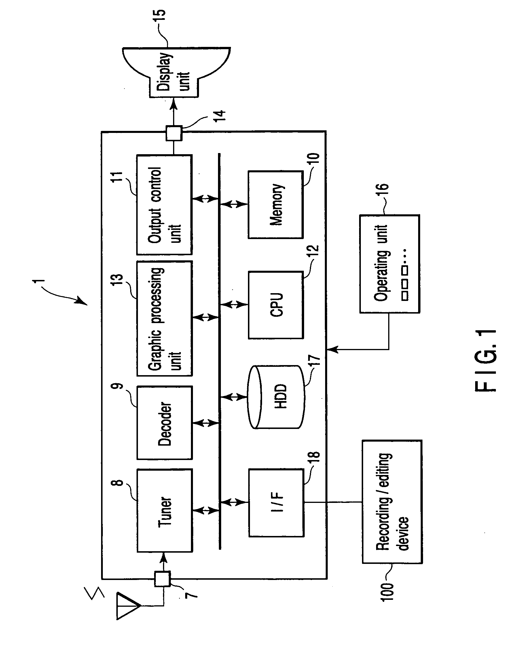
[0026]FIG. 1 is a block diagram showing an example of a system to which a transport stream editing device 100 according to the present invention is applied. The editing device 100 is connected to a TV receiver 1 via an interface (I / F) 18 such as an IEEE1394 interface.

[0027] The TV receiver 1 comprises an input unit 7, a tuner 8, a decoder 9, a memory 10, an output control unit 11, a CPU 12, a graphic processing unit 13, an output unit 14, a display unit 15, an operating unit 16, an HDD 17, and an interface 18.

[0028] To the input unit 7, broadcasting signals received by an antenna are input. From the broadcasting signals input from the input unit 7, specified program data is extracted by the tuner 8. The tuner 8 is a digital tuner that may receive digital broadcasting such as, for example, BS digital. In the embodiment, a case where dig...

second embodiment

[0065] (Second Embodiment)

[0066] Next, a second embodiment of the present invention will be explained hereinafter. The second embodiment is characterized in that the output control information (flags) recorded in the video time information recording unit 108 and the audio time information recording unit 110 in the first embodiment are added to a private data area of a PES header. FIG. 11 is a view showing a structure of a PES header. When a PES extension flag is 1, and a PES private data flag is 1, the PES private data area of 16 bytes becomes effective. By storing output control information into this private data area, it is possible to make data to be recorded into devices only PES data.

[0067]FIG. 12 is a block diagram showing a configuration of an editing device 100 according to the second embodiment, while FIG. 13 is a flowchart showing recording operation according to the second embodiment. In this flowchart, identical codes are allotted to the steps mutually corresponding to ...


PUM


Abstract

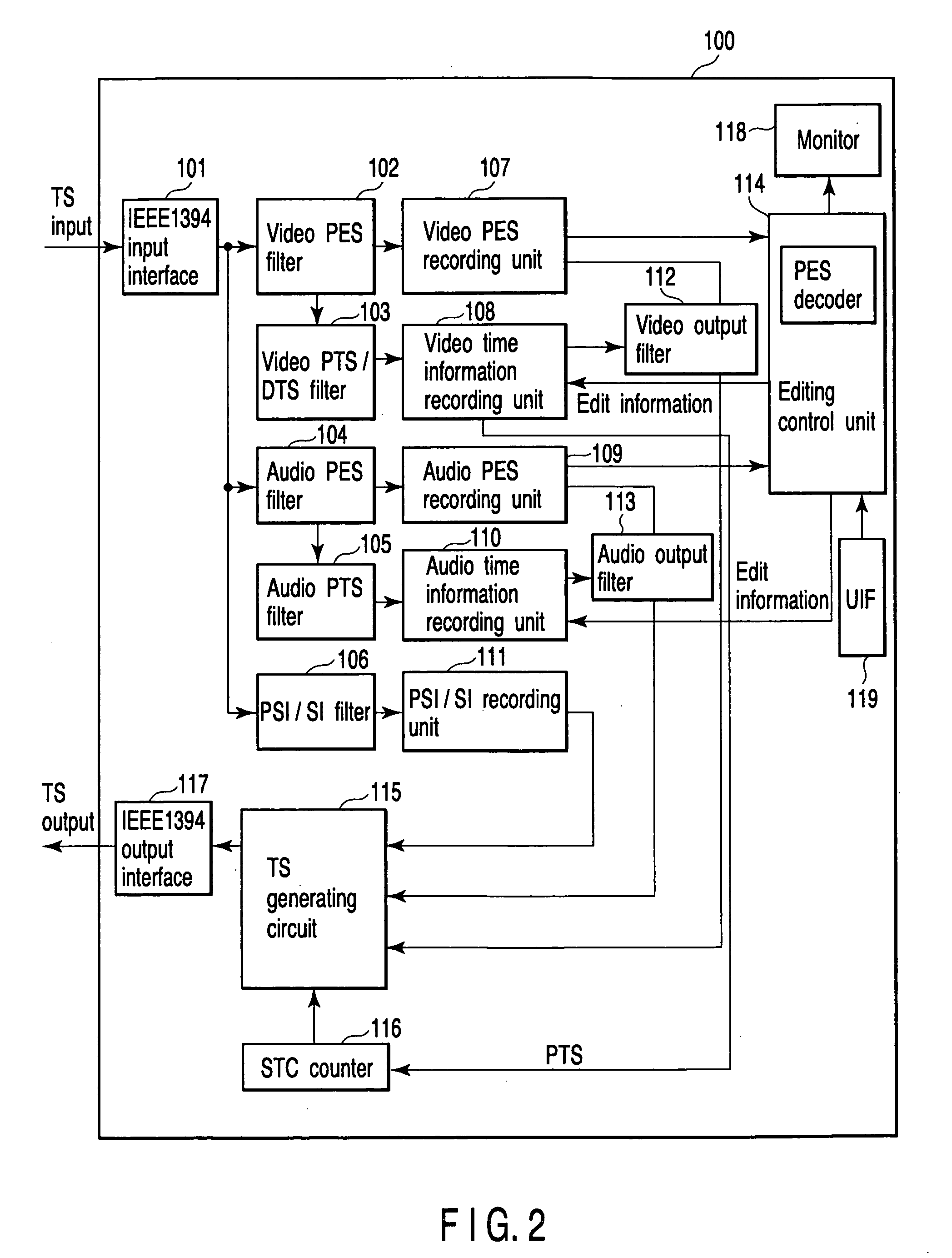
Video ES and audio ES filters extract video and audio payloads from a transport stream. Video ES and audio ES recording units record the payloads as a PES (Packetized Elementary Stream) or an ES (Elementary Stream). An editing control unit edits the ES recorded by the recording units, on the basis of an editing instruction input from a user interface. A TS generating circuit re-converts the ES edited by the editing control unit into a transport stream and outputs the transport stream.

Description

CROSS-REFERENCE TO RELATED APPLICATIONS [0001] This application is based upon and claims the benefit of priority from the prior Japanese Patent Application No. 2003-339983, filed Sep. 30, 2003, the entire contents of which are incorporated herein by reference. BACKGROUND OF THE INVENTION [0002] 1. Field of the Invention [0003] The present invention relates to a recording / editing device that records and / or edits data in MPEG2 transport stream format that is applied to digital broadcasting and the like. [0004] 2. Description of the Related Art [0005] In a transport stream (hereinafter, referred to as a TS) in an MPEG2 system, video and audio compressed encoding strings are multiplexed into a packet of 188 bytes, and data are transmitted in the form of packet strings. However, video packets and audio packets that are multiplexed into a TS are not always synchronized timewise on the stream. Accordingly, it has been difficult to carry out such editing operations as designating a certain ...

Claims


Application Information

Patent Timeline
IPC IPC(8): H04N5/91G11B20/10G11B20/12G11B27/02G11B27/034G11B27/036G11B27/30H04N5/76H04N5/781H04N5/92H04N9/804
CPCG11B27/034G11B27/036G11B27/3027H04N9/8042H04N5/76H04N5/781G11B2220/20
Inventor KUSUNOKI, MAKOTO
Owner KK TOSHIBA
Learn More