Flexible transparent touch sensing system for electronic devices

a technology of electronic devices and touch sensors, applied in static indicating devices, instruments, mechanical pattern conversion, etc., can solve the problems of rugged art and positioning capabilities that require little to no user calibration, and achieve the effect of maximizing transparency, maximizing overlap between each plurality, and maximizing transparency

Inactive Publication Date: 2006-04-18
SYNAPTICS INC
View PDF42 Cites 917 Cited by
  • Summary
  • Abstract
  • Description
  • Claims
  • Application Information

AI Technical Summary

Benefits of technology

[0011]To maximize transparency, the sensor system should have a uniform density of sensor traces. Thus, preferred configurations minimize the overlap of the first plurality and the second plurality of sensor traces. For example, each sensor trace may be configured as a series of diamond shapes aligned along a common axis. Accordingly, each plurality of sensor traces thus creates a pattern of diamond shaped open spaces. By positioning the first plurality of sensor traces over the second plurality so that the diamond shaped sensor traces fall over the diamond shaped open spaces, the amount of overlap between the each plurality of sensor traces is minimized. Transparency is also maximized by utilizing materials having similar indices of refraction.
[0012]A primary object of this invention is a positioning system that uses a low-cost, highly integrated, low power, capacitive transparent sensor. This invention is suitable for many handheld electronic applications such as, but not limited to, cell phones, pagers, personal digital assistants, remote controls, and computers. Non-handheld devices that require a positioning system with a thin transparent sensor are also appropriate for this invention. Preferably, the sensor system is equipped with a processor capable of recognizing gestures such as tapping or dragging to increase the flexibility of user input.
[0013]The current invention described offers a number of advantages over resistiv

Problems solved by technology

First, this art is rugged.
Second, the resolution of sensing is determined by the density of sensor traces and the precision of the A/D converters in the processo

Method used


Image

  • Flexible transparent touch sensing system for electronic devices
  • Flexible transparent touch sensing system for electronic devices
  • Flexible transparent touch sensing system for electronic devices

Examples


Embodiment Construction

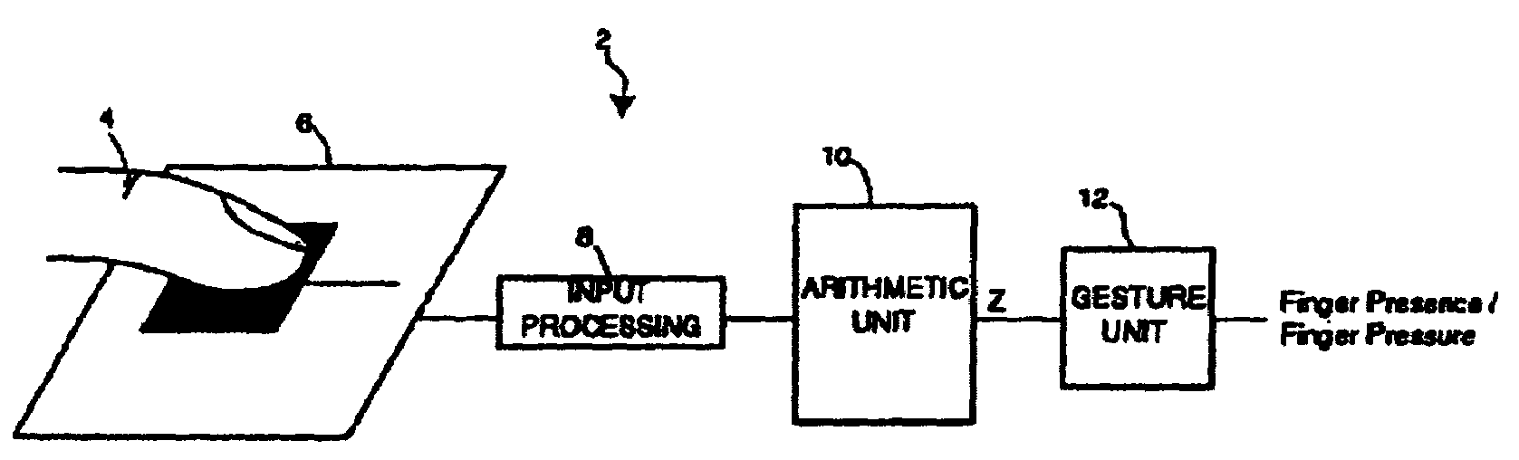
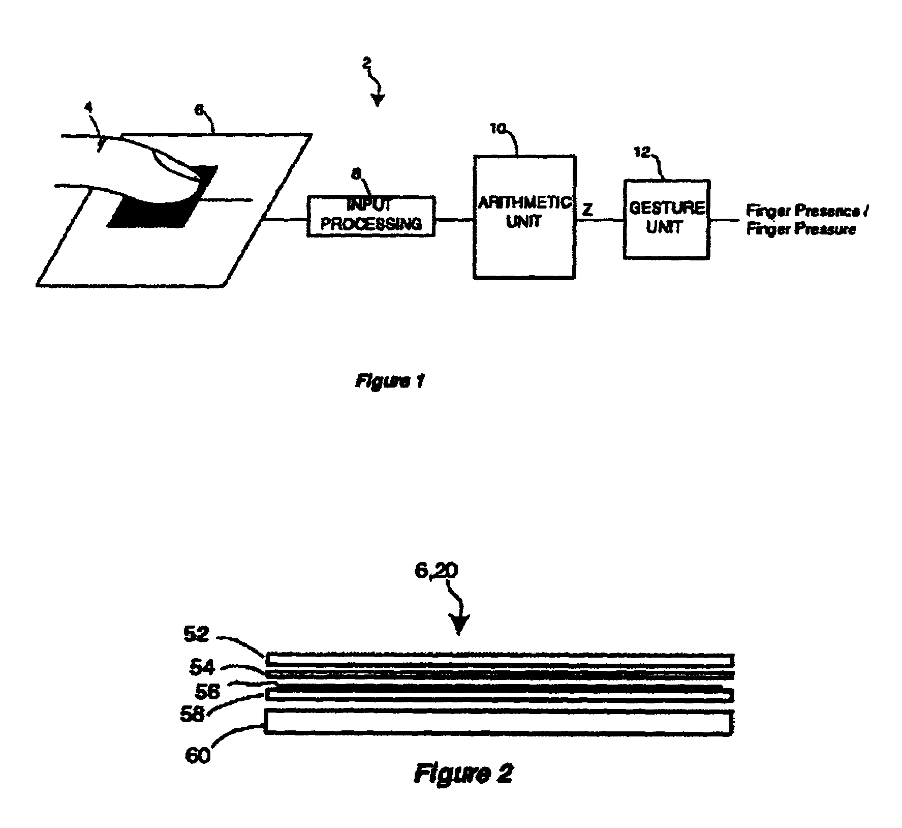
[0026]FIG. 1 is a schematic representation of a preferred embodiment of the invention, comprising a O-dimensional, capacitive proximity sensing system 2. System 2 accurately determines the proximity and contact of finger 4 or any other conductive object to the sensor 6. Capacitance changes induced by finger 4 on the sensor trace in the sensor 6 are digitized by the input processing block 8. The digitized values of capacitance values are processed by arithmetic unit 10 and then decoded by gesture unit 12 to determine if a finger was present. Gesture unit 12 also processes input signals to determine the difference between constant finger contact and a finger tap. Blocks 8–12 may also incorporate methods to suppress electrical noise that may be sensed by sensor 6. Suitable means of implementing this sensor include the technologies described in U.S. Pat. Nos. 5,880,411 and 5,305,017, which were incorporated in their entirety by reference thereto above for these teachings. Other means of...


PUM


Abstract

A transparent, capacitive sensing system particularly well suited for input to electronic devices is described. The sensing system can be used to emulate physical buttons or slider switches that are either displayed on an active display device or printed on an underlying surface. The capacitive sensor can further be used as an input device for a graphical user interface, especially if overlaid on top of an active display device like an LCD screen to sense finger position (X/Y position) and contact area (Z) over the display. In addition, the sensor can be made with flexible material for touch sensing on a three-dimensional surface. Because the sensor is substantially transparent, the underlying surface can be viewed through the sensor. This allows the underlying area to be used for alternative applications that may not necessarily be related to the sensing system. Examples include advertising, an additional user interface display, or apparatus such as a camera or a biometric security device.

Description

BACKGROUND OF THE INVENTION[0001]1. Field of the Invention[0002]The present invention relates to touch sensing transducers and systems. More particularly, the present invention relates to flexible and transparent object position recognition devices useful in applications such as cursor movement and user input for computing devices and other applications.[0003]2. Description of the Related Field[0004]Touch sensing technology can be used to provide a variety of input to electronic devices, from emulating physical buttons or slider switches to more sophisticated recognition of patterns or gestures. For example, U.S. Pat. No. 5,880,411 to Gillespie, which is hereby incorporated in its entirety for its teaching of touch sensor technology, discloses a capacitive sensor trace array object position detector with edge motion feature and gesture recognition. U.S. Pat. No. 5,305,017 to Gerpheide teaches an object position detector using capacitive sensing and is also incorporated in its entire...

Claims


Application Information

Patent Timeline
IPC IPC(8): G09G5/08G06T1/00G06F3/00G06F3/01G06F3/041G06F3/044
CPCG06F3/044G06F3/0445G06F3/0446G06F3/0412
Inventor HSU, ANDREW C.DAY, SHAWN P.SCHEDIWY, RICHARDGILLESPIE, DAVID
Owner SYNAPTICS INC
Why Eureka
Try Eureka