Device for transmitting electromagnetic waves through an aperture in a wall

a technology of electromagnetic waves and apertures, applied in waveguide devices, basic electric elements, electrical apparatus, etc., can solve problems such as failure of dielectric plates, toxic or hazardous, etc., and achieve the effects of reducing the refractive index (n) or dielectric constant, improving the transmission efficiency of invention devices, and improving operational safety

Inactive Publication Date: 2005-01-18
PRAXAIR TECH INC
View PDF4 Cites 2 Cited by
  • Summary
  • Abstract
  • Description
  • Claims
  • Application Information

AI Technical Summary

Benefits of technology

In accordance with another aspect, the gap or the third layer between the two layers / plates may be equipped with a pressure sensing port to accommodate a pressure sensor. The pressure sensor monitors the structural integrity of the dielectric layers / plates and improves operational safety. In a preferred embodiment of the invention, a pressure-sensing device connected to the pressure sensing port shuts the microwave or vaporizing system down in the event of a pressure breach of the dielectric layer / plate or gasket material in contact with the high-pressure vessel.
In the preferred embodiment of the invention, a gold plated sleeve or flange is positioned between the dielectric layer / plate in contact with the vessel's content and the wall of the vessel. This further improves the transmission efficiency of the invention device.
A further object of the present invention is to provide material of construction and geometric configuration, which minimize the refractive index (n) or dielectric constant (n2) and dielectric loss (ε″), which results in heat production. Metal parts include aluminum or other suitable conductive metal for main docking collar sections and interface with a stainless steel sleeve with gold plating or conductive plating that coats the sleeve's inner surface conducting microwaves. All metal surfaces meet ASME pressure handling requirements and are compatible with fluid in the vessel. Gasket material is also compatible with the fluid in the vessel, nearly transparent to microwaves, and provides a good pressure seal.

Problems solved by technology

The gases are usually under moderate to high pressure and can be toxic or hazardous if exposed to the atmosphere.
On the other hand, the existing stresses can cause failures of the dielectric plates.

Method used


Image

  • Device for transmitting electromagnetic waves through an aperture in a wall
  • Device for transmitting electromagnetic waves through an aperture in a wall
  • Device for transmitting electromagnetic waves through an aperture in a wall

Examples


Embodiment Construction

A description of preferred embodiments of the invention follows.

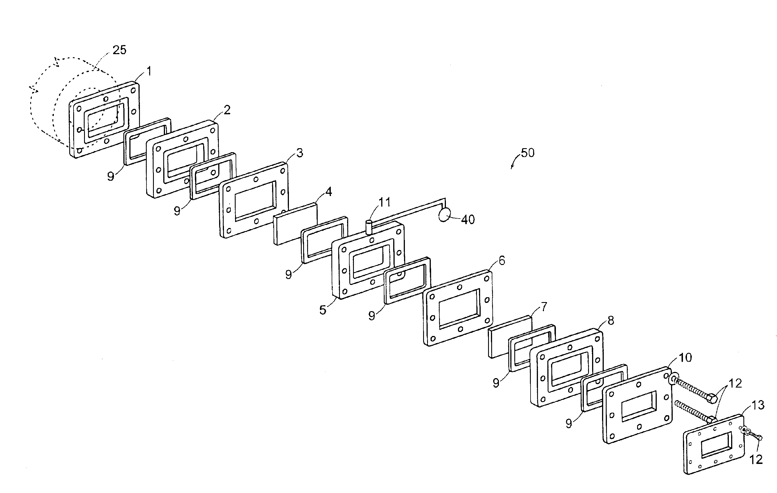
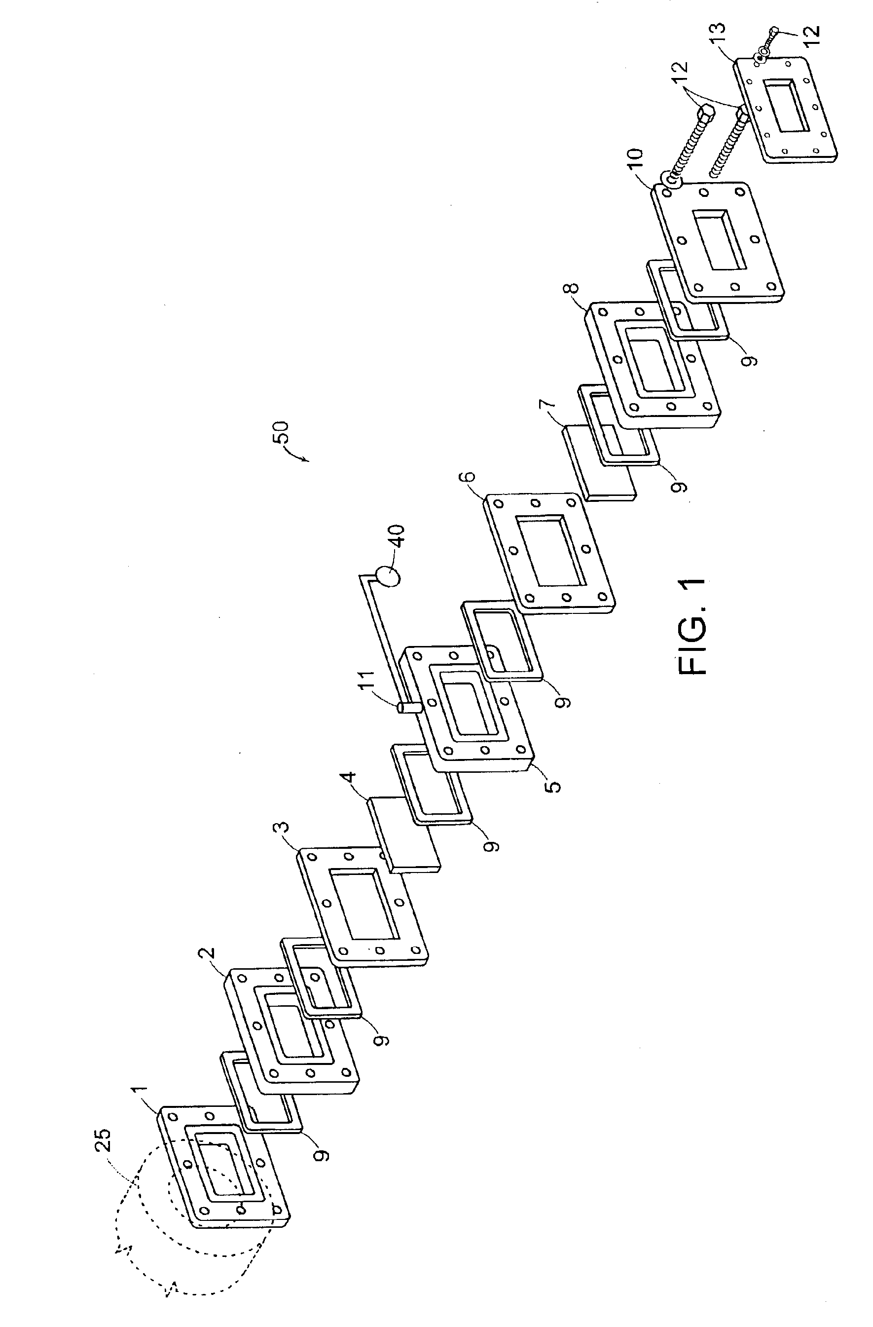
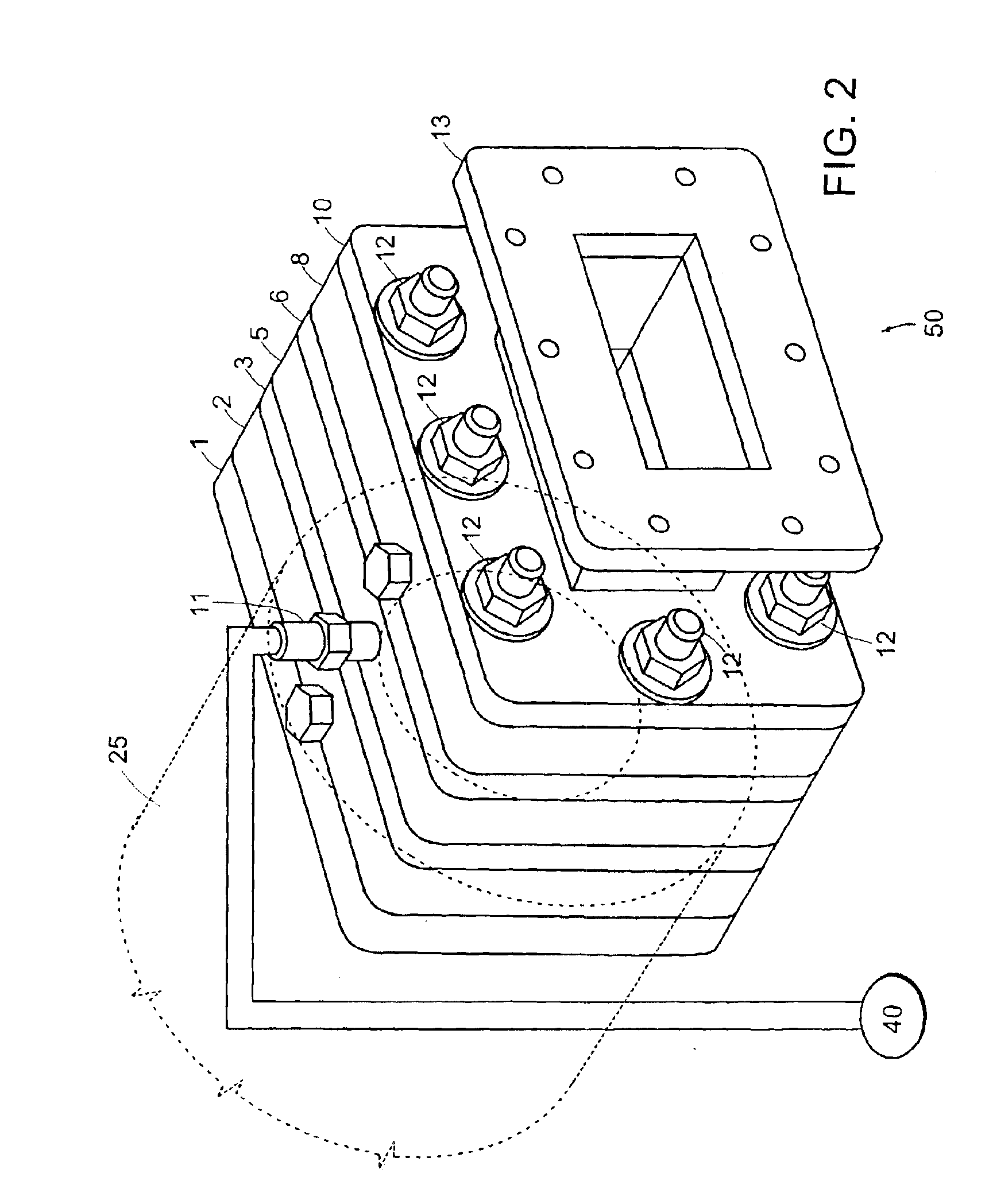
FIGS. 1 and 2 show a preferred embodiment of the invention for microwave evaporation of liquid NH3 in a pressurized stainless steel vessel with a capacity of approximately 300 gallons under pressure of up to 265 pounds per square inch and temperature of up to 200° C. Microwaves within the range of 2425 to 2475 MHz generated by a 30 kW microwave generator (e.g., a magnetron) enter the device 50 via a section of a waveguide 13 through an aluminum docking collar 10 and an aluminum flange 8. As shown in FIG. 1, the microwaves pass through a dielectric plate 7 mounted in an aluminum frame 6 orthogonal to the microwaves' trajectory. After passing through the dielectric plate 7, the microwaves pass through the gap formed by an aluminum collar 5 and then pass through a second dielectric plate 4 mounted in a respective aluminum frame 3 orthogonal to the microwaves' trajectory. The framed dielectric plates 4 and 7 serve as dual w...


PUM


Abstract

A device for efficient transmission of electromagnetic waves comprising two layers of dielectric separated by a gap or space. The layers may be uniform or laminar, orthogonal or non-orthogonal to the direction of wave propagation, and made of Teflon, quartz, polypropylene, and the like. The preferred distance between layers is an odd multiple of quarter wavelength in the environment between the layers. The preferred thickness of the layers is an odd multiple of half of the effective wavelength for the layer. The device allows over 95% efficiency for transmission into a pressurized vessel for evaporation under high pressure and temperature and does not require a cooling system. The separating space may be connected with a pressure-sensing subsystem to monitor the device's integrity and shut down the system in the event of a breach. A sleeve connecting the device to the vessel may be coated with conductive material for improved efficiency.

Description

BACKGROUND OF THE INVENTIONThis invention generally relates to transmission of electromagnetic waves between two regions divided by a solid window penetrable by the electromagnetic waves. The electromagnetic properties of the window are generally different from the properties of the matter that makes contact with the windows. The general purpose is to transmit through the window the maximum amount of energy carried by the electromagnetic waves, i.e., to minimize the dispersion, reflection, and dissipation, at the same time maintaining the structural integrity of the window.More specifically, a microwave-based evaporator / vaporizer has a waveguide coupled to a high-pressure vessel. A docking collar safety device is positioned between the waveguide and the high-pressure vessel. The evaporator / vaporizer system vaporizes liquefied compressed gases such as ammonia (or other similar liquid) at high flow rates. The gases are usually under moderate to high pressure and can be toxic or hazard...

Claims


Application Information

Patent Timeline
Patent Type & Authority Patents(United States)
IPC IPC(8): H01P1/08
CPCH01P1/08
Inventor APTE, PRASADISOM, WENDELL W.LITWIN, MICHAEL M.
Owner PRAXAIR TECH INC
Why Eureka
Try Eureka