Spin orbit torque magnetic RAM

a magnetic ram and spin orbit technology, applied in the field of spin orbit torque magnetic random access memory, to achieve the effect of reducing the driving current density j

Active Publication Date: 2021-01-05
KOREA INST OF SCI & TECH
View PDF6 Cites 1 Cited by
  • Summary
  • Abstract
  • Description
  • Claims
  • Application Information

AI Technical Summary

Benefits of technology

[0009]Accordingly, the present invention has been made keeping in mind the above problems occurring in the related art, and an object of the present invention is to provide a spin orbit torque magnetic RAM that is operated in such a manner as to maintain a tendency of increasing and decreasing of a magnetic damping constant α and a tendency of increasing and decreasing of a spin Hall angle θSH in a free layer in opposite to each other thereby reducing a driving current density JC, in a row select line, a free layer, a tunnel barrier, a pinned layer, and a column select line that are sequentially stacked, even if the spin selectivity is high at an interface between the row select line and the free layer.
[0017]The first magnetic pattern and the second magnetic pattern may maximize spin transparency at an interface between the row select line and the first magnetic pattern, and minimize two-magnon electron scattering at an interface between the second magnetic pattern and the tunnel barrier.
[0018]The row select line may generate spin current from a first current in-plane due to the spin orbit interaction and then transmit the spin current sequentially to the first magnetic pattern and the second magnetic pattern, while the first current flows through a row line power supply (VR), and transmit an angular momentum of the spin current to a lower magnetization that is a total magnetic moment of the first magnetic pattern and the second magnetic pattern, so that the lower magnetization of the first magnetic pattern and the second magnetic pattern may be changed in direction to be parallel or anti-parallel to an upper magnetization of the third magnetic pattern, thereby performing a data write operation.
[0021]The present invention includes the row select line, the free layer, the tunnel barrier, the pinned layer, and the column select line that are sequentially stacked, in which at least two magnetic patterns are sequentially stacked in the free layer, whereby a tendency of increasing and decreasing of the magnetic damping constant α at an interface between the row select line and the free layer and a tendency of increasing and decreasing of the spin Hall angle θSH at an interface between the free layer and the tunnel barrier are maintained opposite to each other, thereby reducing the driving current density JC.

Problems solved by technology

This is because there a problem that the external magnetic field-based magnetic RAM does not resolve that the size of the memory cell (including the magnetic tunnel junction) is inversely proportional to the magnitude of the external magnetic field, and thus half-selects the remaining memory cells other than one specific memory cell located at the intersection area of a row line and a column line during selecting the memory cell through orthogonalization of the row line and the column line.

Method used


Image

  • Spin orbit torque magnetic RAM
  • Spin orbit torque magnetic RAM
  • Spin orbit torque magnetic RAM

Examples


Embodiment Construction

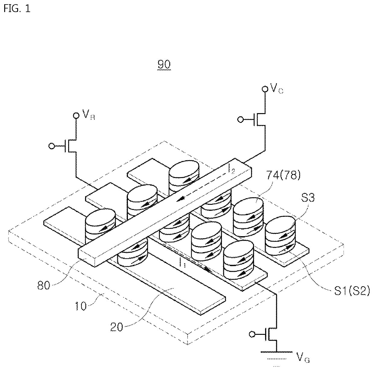
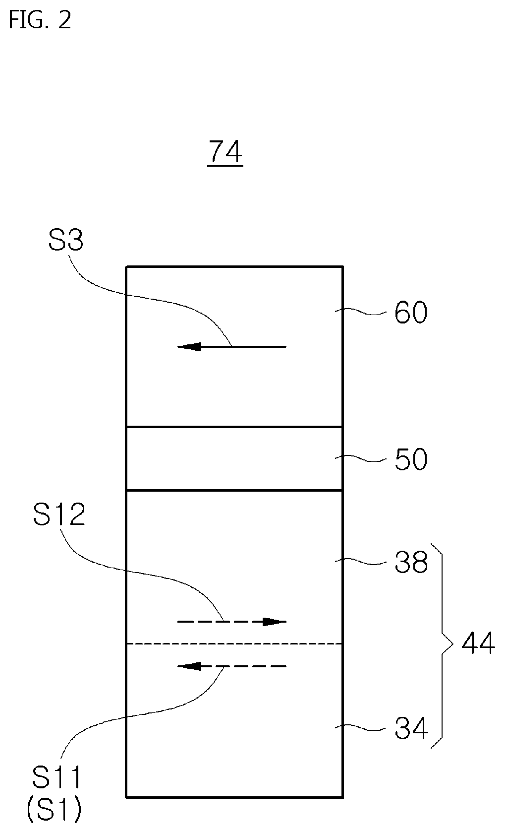
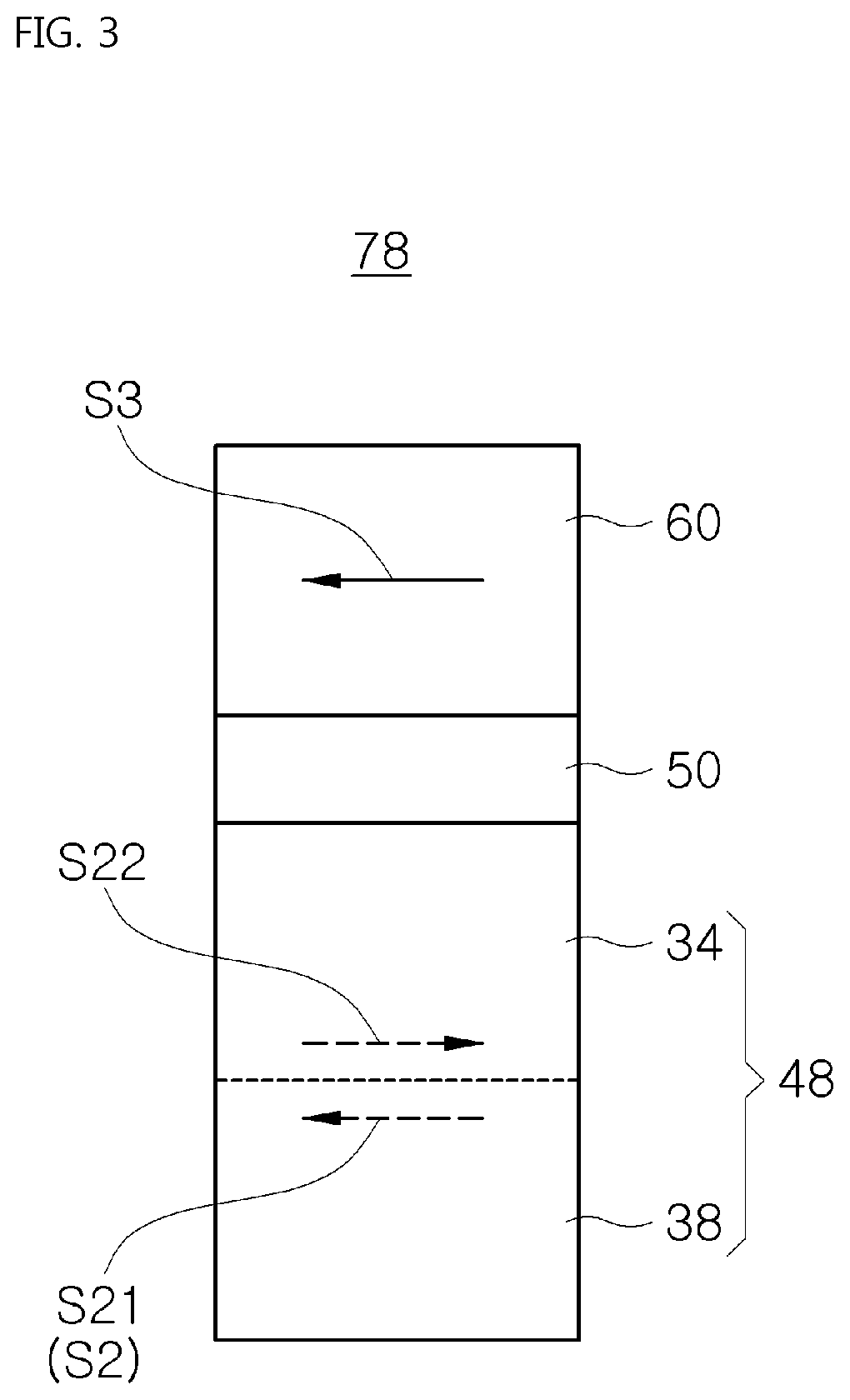
[0030]The following detailed description of the invention refers to the accompanying drawings, which illustrate, by way of example, specific embodiments in which the invention may be practiced. These embodiments are described in sufficient detail to enable those skilled in the art to practice the invention. It should be understood that the various embodiments of the present invention are different, but need not be mutually exclusive. For example, certain features, structures, and characteristics described herein may be implemented in other embodiments without departing from the spirit and scope of the invention in connection with one embodiment. It is also to be understood that the position or arrangement of the individual components within each disclosed embodiment may be varied without departing from the spirit and scope of the invention. The following detailed description is, therefore, not to be taken in a limiting sense, and the scope of the present invention is to be limited o...


PUM

PropertyMeasurementUnit
thicknessaaaaaaaaaa
driving current densityaaaaaaaaaa
thicknessaaaaaaaaaa

Abstract

A spin torque magnetic RAM according to the present invention includes at least one row selection line positioned on a silicon substrate to induce a spin orbit interaction therein; at least one first magnetic pattern positioned on the row selection line; a second magnetic pattern positioned on the first magnetic pattern; a tunnel barrier positioned on the second magnetic pattern; and a third magnetic pattern positioned on the tunnel barrier, wherein the first magnetic pattern is made of a cobalt film, the first magnetic pattern and the second magnetic pattern have a total thickness of 5 nm to form a free layer, and the third magnetic pattern is formed with a pinned layer in which a magnetization direction is fixed.

Description

CROSS REFERENCE TO RELATED APPLICATION[0001]The present application claims priority to Korean Patent Application No. 10-2017-0162573, filed on Nov. 30, 2017, the entire contents of which is incorporated herein for all purposes by this reference.BACKGROUND OF THE INVENTIONField of the Invention[0002]The present invention relates to a spin orbit torque magnetic random access memory (RAM) in which a free layer of a magnetic tunnel junction (MTJ) is double-stacked at a memory cell driven by a spin orbit torque to cause a physical parameter to be controlled according to an accumulating order thereof, thereby controlling an electric current density consumed in the free layer.Description of the Related Art[0003]Recently, a magnetic RAM has been manufactured in such a manner that the magnetization of the free layer is changed to be parallel or anti-parallel to the magnetization of a pinned layer, by using a spin transfer torque (STT) or a spin orbit torque (SOT) caused within a magnetic tun...

Claims


Application Information

Patent Timeline
Patent Type & Authority Patents(United States)
IPC IPC(8): G11C11/16H01L43/02H01L43/10H01L27/22G11C11/18
CPCH01L43/02G11C11/161G11C11/1655G11C11/1657G11C11/1659G11C11/18H01L27/228H01L43/10G11C11/1673G11C11/1675H10B61/22H10N50/85H10N50/10H10N50/80
Inventor LEE, OUKJAEMIN, BYOUNG-CHUL
Owner KOREA INST OF SCI & TECH
Why Eureka
Try Eureka