Image forming apparatus

Inactive Publication Date: 2005-03-31
KONICA MINOLTA BUSINESS TECH INC
View PDF6 Cites 22 Cited by
  • Summary
  • Abstract
  • Description
  • Claims
  • Application Information

AI Technical Summary

Benefits of technology

[0009] The object of the present invention is to provide an image forming apparatus which enables an image of high quality to be formed without reducing

Problems solved by technology

However, when an image forming operation is started during or immediately after the switching process, a possible vibration of the intermediate transfer belt due to the switching process might result in image noise.
In particular, when the device is switched from the monochrome mode to the color mode, one or more photoreceptor drums are brought into contact with the intermediate transfer belt, which produces a vibration leading to an inappropriate overlapp

Method used


Image

  • Image forming apparatus
  • Image forming apparatus
  • Image forming apparatus

Examples


first embodiment

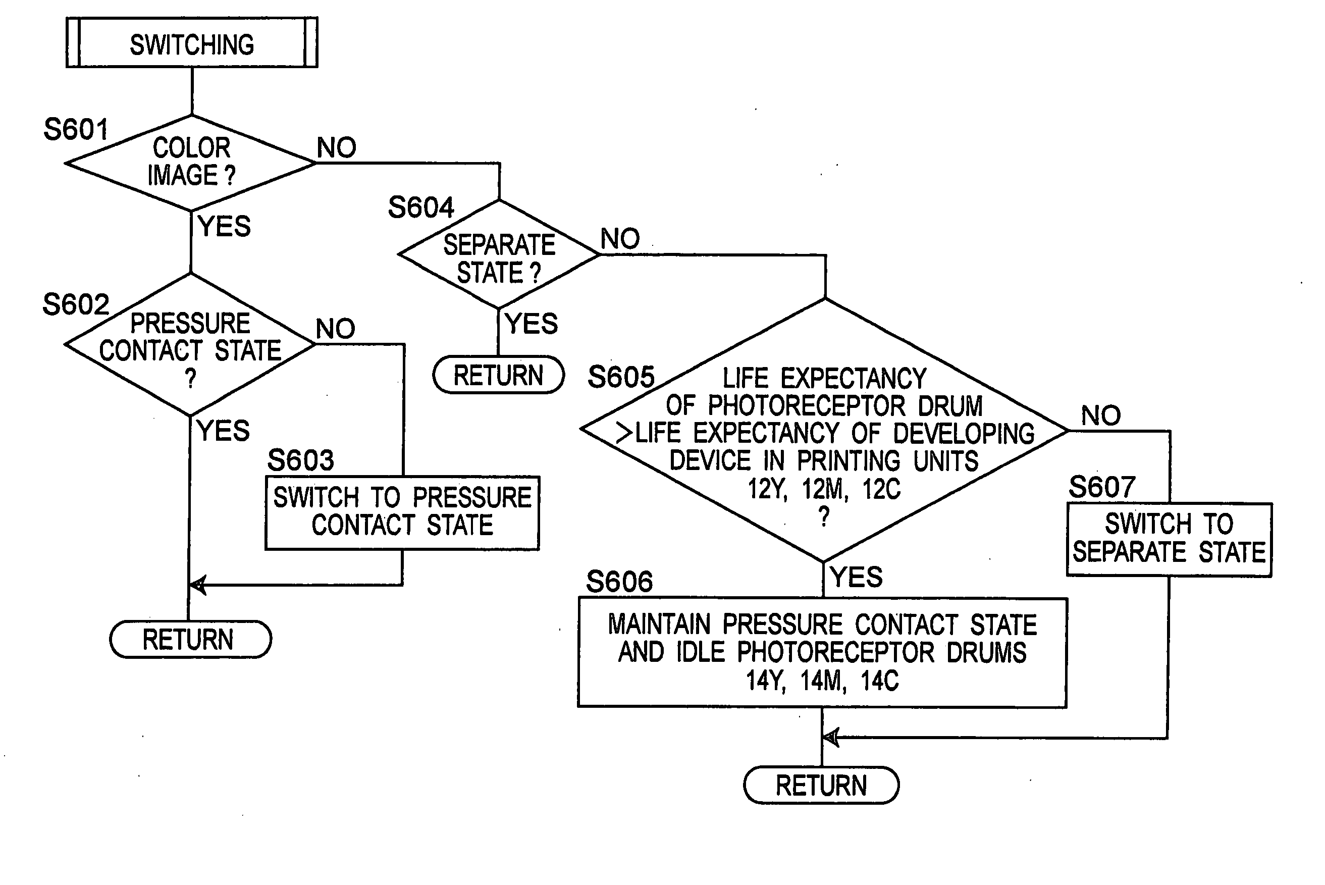
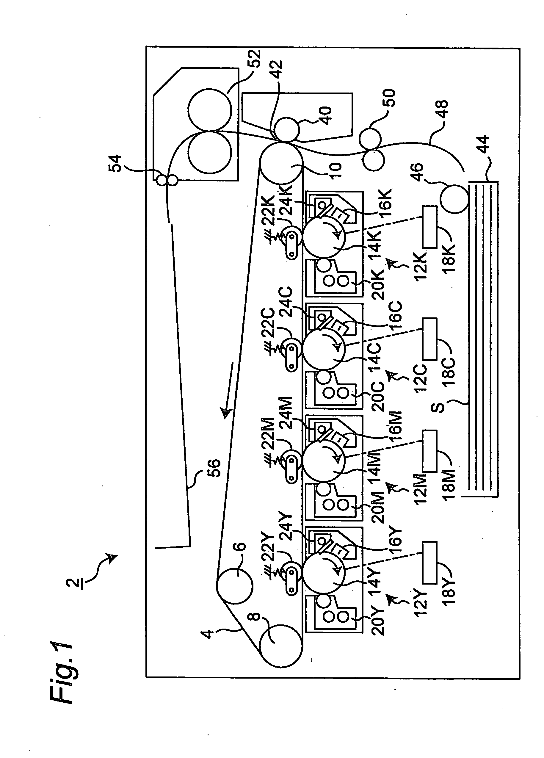
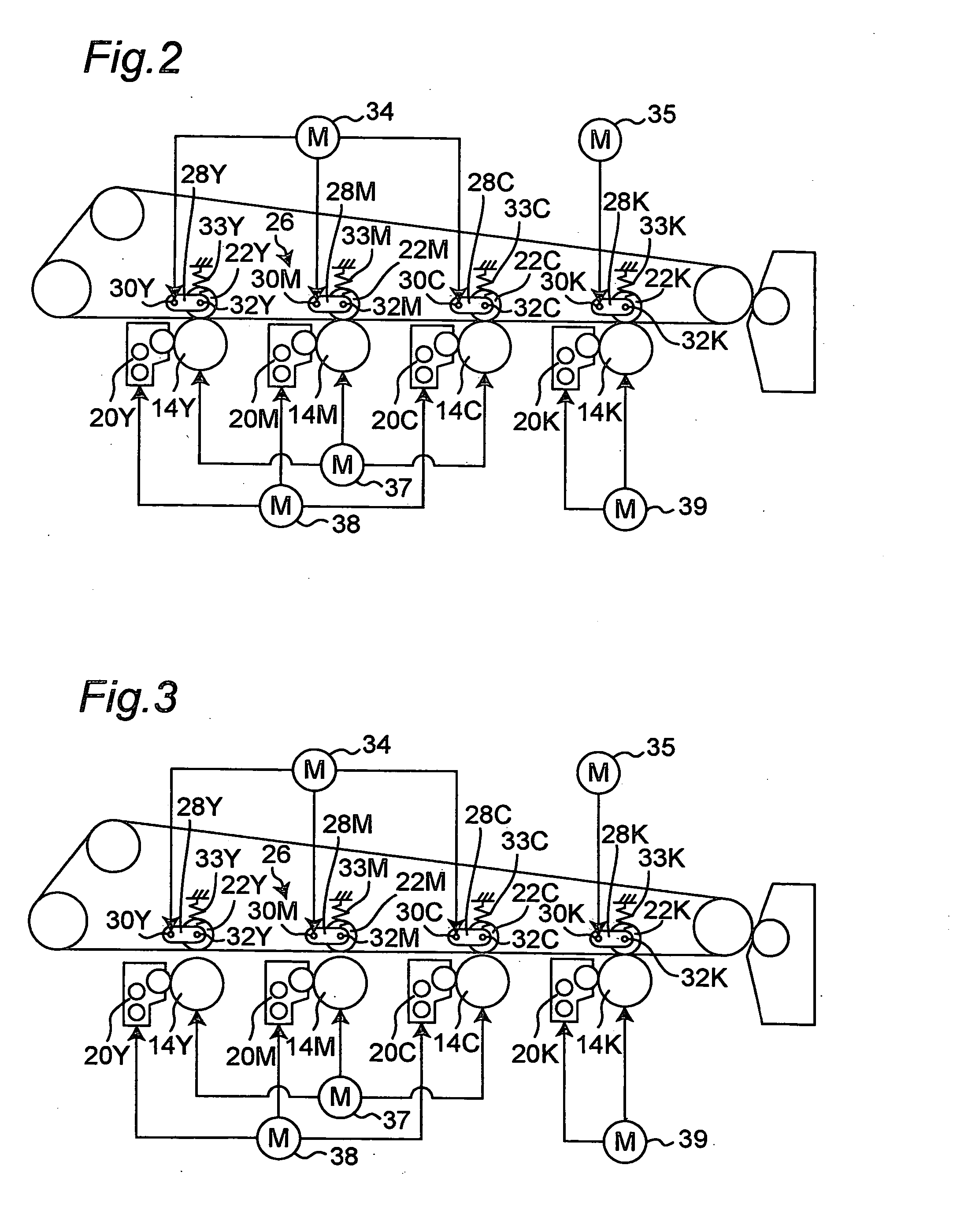
[0025] First Embodiment

[0026] Referring to FIG. 1, there is shown a tandem-type color printer, which is a first embodiment according to the present invention. The printer, generally indicated at reference number 2, includes an intermediate transfer belt 4 as transfer member, which is located generally at the center of the interior thereof. The intermediate transfer belt 4 is supported by the circumferences of three rollers 6, 8 and 10. The roller 6 is a tension roller that provides tension to the intermediate transfer belt 4. The roller 10 is operatively connected with a drive motor not shown. The rotation of the roller 10 causes the rollers 6 and 8 to rotate so that the intermediate transfer belt 4 is rotated in the counterclockwise direction of the drawing.

[0027] Four printing units 12Y, 12M, 12C and 12K for yellow(Y), magenta(M), cyan(C) and black(K), respectively, are arranged along the intermediate transfer belt 4 under the lower horizontal portion of the belt 4.

[0028] As ima...

second embodiment

[0066] Second Embodiment

[0067] An image forming device of a second embodiment according to the present invention will now be described. The image forming device is a printer similar to the printer 2 shown in FIGS. 1-4 except that, in case of a print job including more than one documents, the printer controller 66 calculates how many times color document(s) and monochrome document(s) are alternated in the order of printing and then calculates a ratio of the “number of alternate times” to the number of the documents. The number of alternate times is stored in the color / monochrome information memory 69 in the main controller 36.

[0068] More specifically, with reference to FIGS. 1, 4 and 7-9, an RGB image signal representative of a given number of documents is first transmitted from the external terminal to the printer controller 66 in the printer 2 (step 701), the image processor 84 generates YMCK image data consisting of yellow, magenta, cyan and black components document by document ...


PUM


Abstract

An image forming apparatus includes a plurality of printing units each having an image bearing member for rotation about an axis and a process member which cooperates with the image bearing member in an image forming process; a transfer member for moving in contact with the image bearing member of each of the plurality of printing units, an image on each of the image bearing members being transferred onto the transfer member or a recording medium that is transported on the transfer member; a switch unit for switching between a contact state where the image bearing members in the plurality of printing units are in contact with the transfer member and a separate state where the image bearing member(s) in the printing unit(s) other than one of the plurality of printing units are separated from the transfer member; a memory for storing life expectancies of the image bearing member and the process member with regard to the printing unit(s) other than the one of the plurality of printing units; and a control section for controlling the switch unit based on a print job and the life expectancies stored in the memory.

Description

RELATED APPLICATION [0001] This application is based on Japanese Patent Application No. 2003-333322, the content of which being incorporated herein by reference. BACKGROUND OF THE INVENTION [0002] 1. Field of the Invention [0003] The present invention relates to an image forming apparatus such as printer, copying machine, facsimile or multifunction peripheral having functions of printing, copying, faxing and the like, and more particularly a tandem-type color image forming apparatus. [0004] 2. Description of the Related Art [0005] There has been known a tandem-type color image forming device in which four photoreceptor drums for cyan, magenta, yellow and black are aligned along an intermediate transfer belt. Cyan, magenta, yellow and black toner images are first formed on the photoreceptor drums, respectively, and then transferred onto the intermediate transfer belt (which is referred to as primary transfer process) such that they overlap each other to form a color toner image. Next...

Claims


Application Information

Patent Timeline
IPC IPC(8): G03G21/00G03G15/01
CPCG03G15/0131G03G2215/0119G03G2221/1823G03G2221/1663G03G2215/0154G03G15/0136
Inventor HASHIMOTO, JUNICHIYOSHIZAWA, KYOICHIMIZUNO, HIROSHIIMURA, TOMOYUKIUENO, HIROMASAYAMADA, TAKANOBU
Owner KONICA MINOLTA BUSINESS TECH INC
Why Eureka
Try Eureka