Machine tool

a technology of machine tools and tools, applied in the field of machine tools, can solve the problems of long time and many work to remove chips introduced into the t slots, and load cleaning work, and achieve the effect of reducing the cleaning work of the tabl

Inactive Publication Date: 2005-03-31
DMG MORI SEIKI CO LTD
View PDF16 Cites 15 Cited by
  • Summary
  • Abstract
  • Description
  • Claims
  • Application Information

AI Technical Summary

Benefits of technology

[0018] In the machine tool according to the present invention, chips splashed down onto the table arranged substantially in a horizontal dir...

Problems solved by technology

For this reason, it takes long time and much work to remove the c...

Method used


Image

  • Machine tool
  • Machine tool
  • Machine tool

Examples


Embodiment Construction

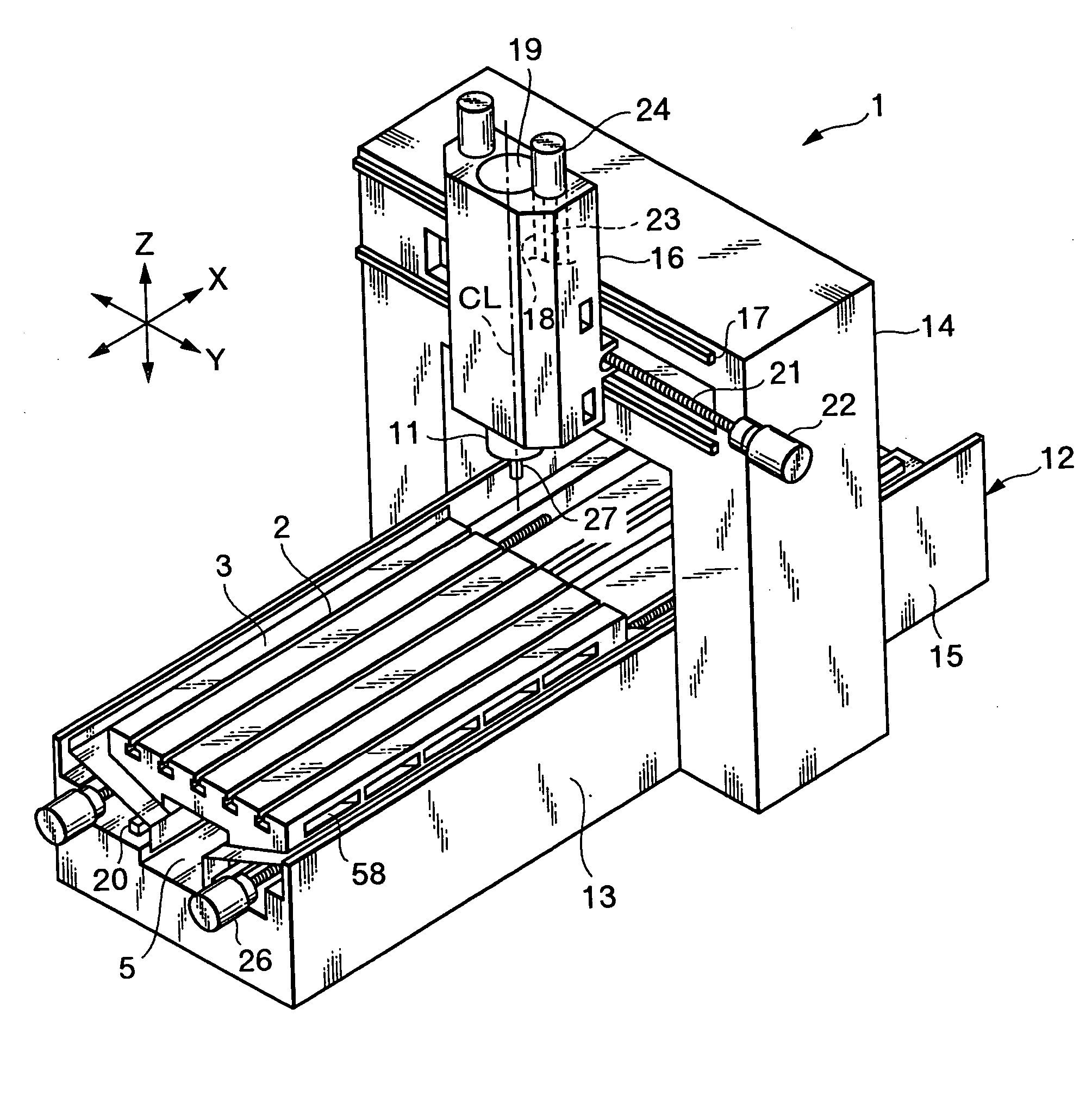
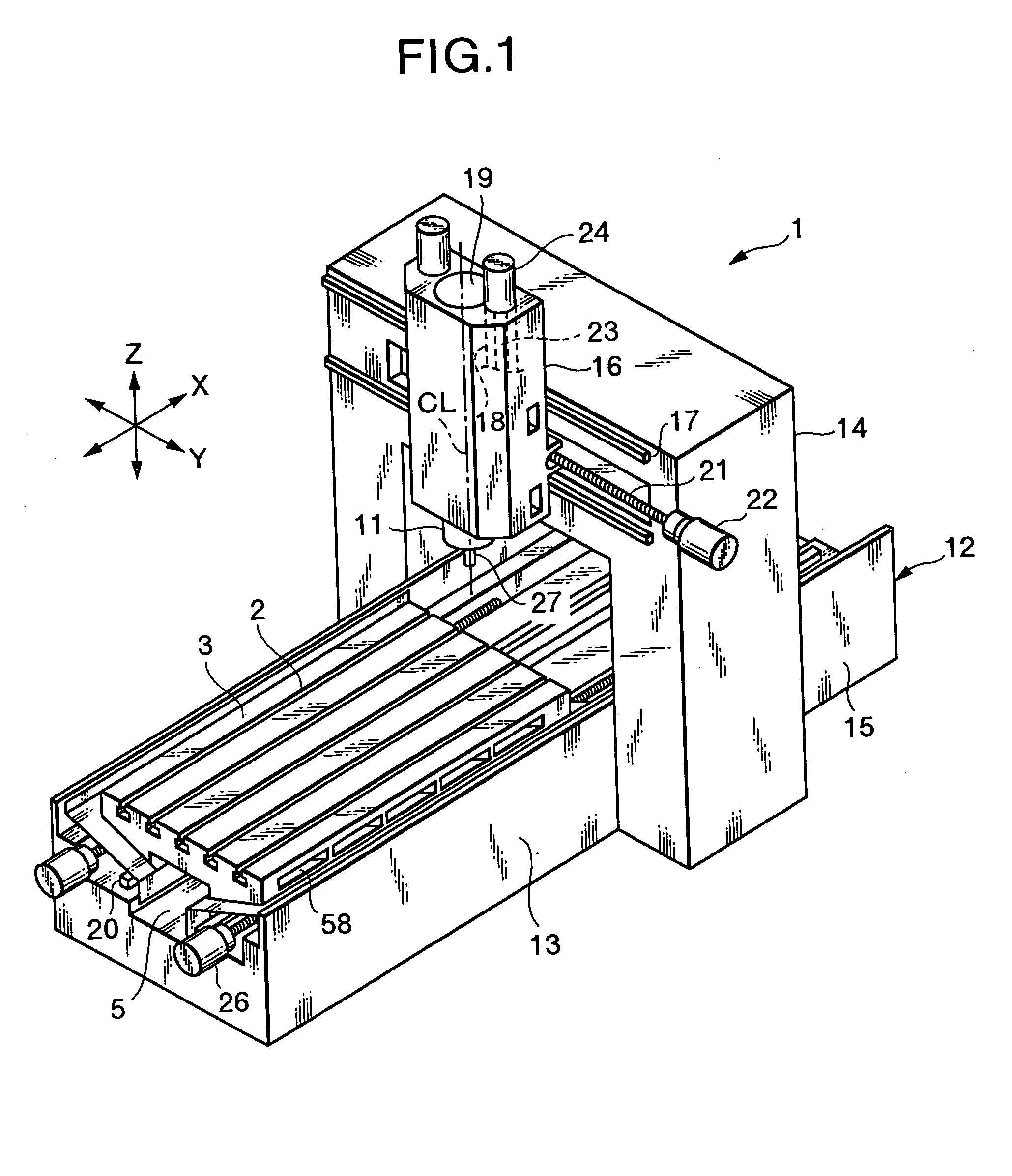
[0023] In a machine tool according to the present invention, a table having a plurality of T slots on its top surface (or having no T slots) is arranged substantially in a horizontal direction. A lower space into which chips may be received is provided under the table of the machine tool. As such a machine tool, the following embodiment shows a double housing MC (double housing machining center) out of MCs.

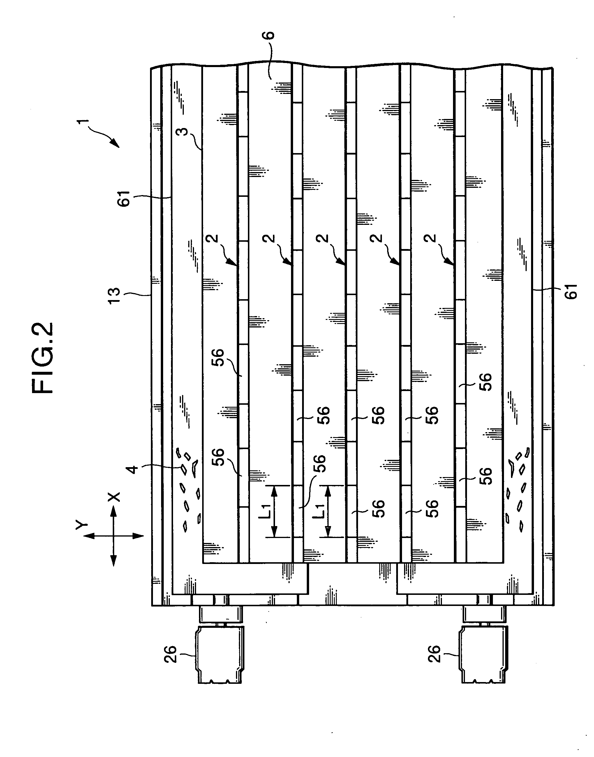
[0024] According to the invention, an object to remove the chips introduced into the T slots or the like of the table is attained by a simple structure in which a plurality of through-holes, which are in fluid communication with bottom portions of the T slots and pass through the table to reach the lower space, is scattered and formed in the table.

[0025] Also, an object of the present invention is to cause the chips remaining on the table to pass to the lower space after scavenging the chips from outer circumferential edges of the table to the outside, thereby completing the cle...


PUM


Abstract

In a double housing machining center, a table having a plurality of T slots on its top surface is arranged substantially in a horizontal direction. A lower space, into which chips are received, is provided under the table. A plurality of through-holes, being in fluid communication with bottom portions of the T slots and passing through the table to reach the lower space, is scattered and formed in the table. The chips introduced into the T slots are discharged into the lower space through the through-holes. Thus, the chips splashed down onto the table and introduced into the T slots are readily removed and the cleaning work of the table is reduced.

Description

BACKGROUND OF THE INVENTION [0001] 1. Field of the Invention [0002] The present invention relates to a machine tool such as a machining center (hereinafter referred to as MC) having a table, and more particularly to a machine tool which may readily remove chips splashed down onto the table and introduced into T slots of the like of the table. [0003] 2. Description of the Related Art [0004] In an MC out of machine tools, in many cases, there is provided with a table arranged substantially in a horizontal direction. Normally, T slots are formed on a top surface of the table. [0005] For example, a double housing MC (double housing machining center) having the table arranged substantially in the horizontal direction is disclosed in Japanese Utility Model Application Laid-Open No. 5-26245, Japanese Patent Application Laid-Open No. 6-71533, Japanese Patent Application Laid-Open No. 8-267320, Japanese Patent Application Laid-Open No. 10-286734, Japanese Patent Application Laid-Open No. 11-...

Claims


Application Information

Patent Timeline
IPC IPC(8): B23C1/00B23Q1/00B23Q1/01B23Q1/03B23Q11/00
CPCB23C1/002B23Q11/0053Y10T409/30868Y10T409/304088Y10S29/101
Inventor FUJIWARA, RYUICHI
Owner DMG MORI SEIKI CO LTD
Why Eureka
Try Eureka