Connecting structure for electric cells

a technology of connecting structure and electric cell, which is applied in the direction of cell components, cell component details, coupling device connections, etc., can solve the problems of increasing shortening the life of electric cells, and affecting the efficiency of electric cells, so as to avoid damage to electric cells, reduce the number of areas, and reduce the effect of electric resistance of the connecting ring

Inactive Publication Date: 2005-03-31
HONDA MOTOR CO LTD
View PDF25 Cites 43 Cited by
  • Summary
  • Abstract
  • Description
  • Claims
  • Application Information

AI Technical Summary

Benefits of technology

[0026] Further, of the second flange section of the connecting ring to be welded to the seal plate, at least portions to be welded to the seal plate are thinner than the seal plate. Therefore, even when external force which would pull off the connecting ring from the electric cells is applied to the connecting ring, the connecting ring is made more susceptible to damages, thereby avoiding infliction of damages to the electric cells. Further, the connecting ring exclusive of the weld sections of the large-diameter short cylindrical section and the second flange section is set to be greater in thickness than a thicker one of the weld sections of the large-diameter short cylindrical section and those of the second flange section. Accordingly, a thickness of the connecting ring exclusive of the weld sections to the electric cells is relatively thick, and electric resistance of the connecting ring can be suppressed to a relatively low level. As a result, even when a large amount of current is charged or discharged from the electric cells, a voltage drop developing in the connecting ring can be suppressed to a low level, to thus increase output. In addition, heat development in the connecting ring can be avoided, thereby prolonging the lives of the electric cells.
[0027] According to the invention of the second aspect, a stable welding characteristic can be ensured during protrusive welding of the large-diameter short cylindrical section of the connecting ring to the bottomed cyliner of the electric cells, whereby electric resistance of a connecting portion between the connecting ring and the electric cell can be suppressed to a low level.

Problems solved by technology

In this case, when a large amount of current is charged or discharged from the electric cells, a drop in voltage at the connecting ring becomes large.
This may result in inability to take out large electric power or heat development at the connecting bus bar responsible for heating the electric cells, which may shorten the lives of the electric cells.
Such a connecting bus bar involves an increase in the number of areas to be welded, which is responsible for a cost hike, and an increase in the weight of the connecting structure, as well as involving an increase in the number of components to be used for constituting the bus bar.
In this case, when a large amount of current is charged or discharged from the electric cells, a drop in voltage at the connecting bus bar becomes large.
This may result in inability to take out large electric power or heat development at the connecting ring responsible for heating the electric cells, which may shorten the lives of the electric cells.

Method used


Image

  • Connecting structure for electric cells
  • Connecting structure for electric cells
  • Connecting structure for electric cells

Examples


first embodiment

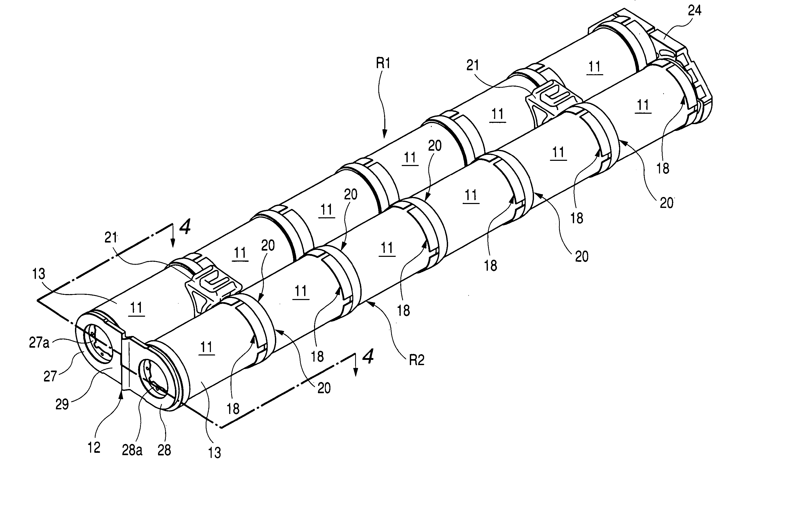
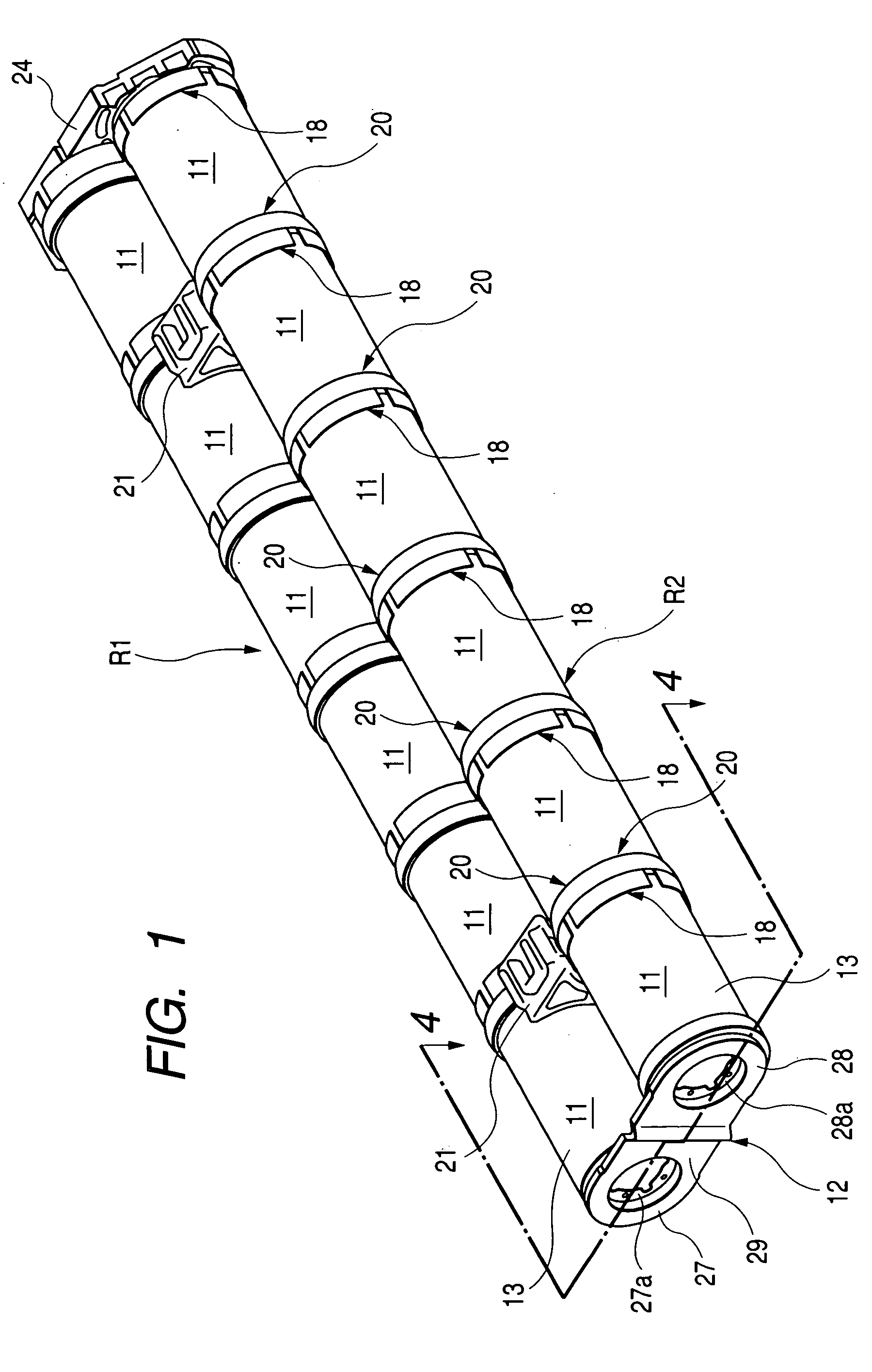
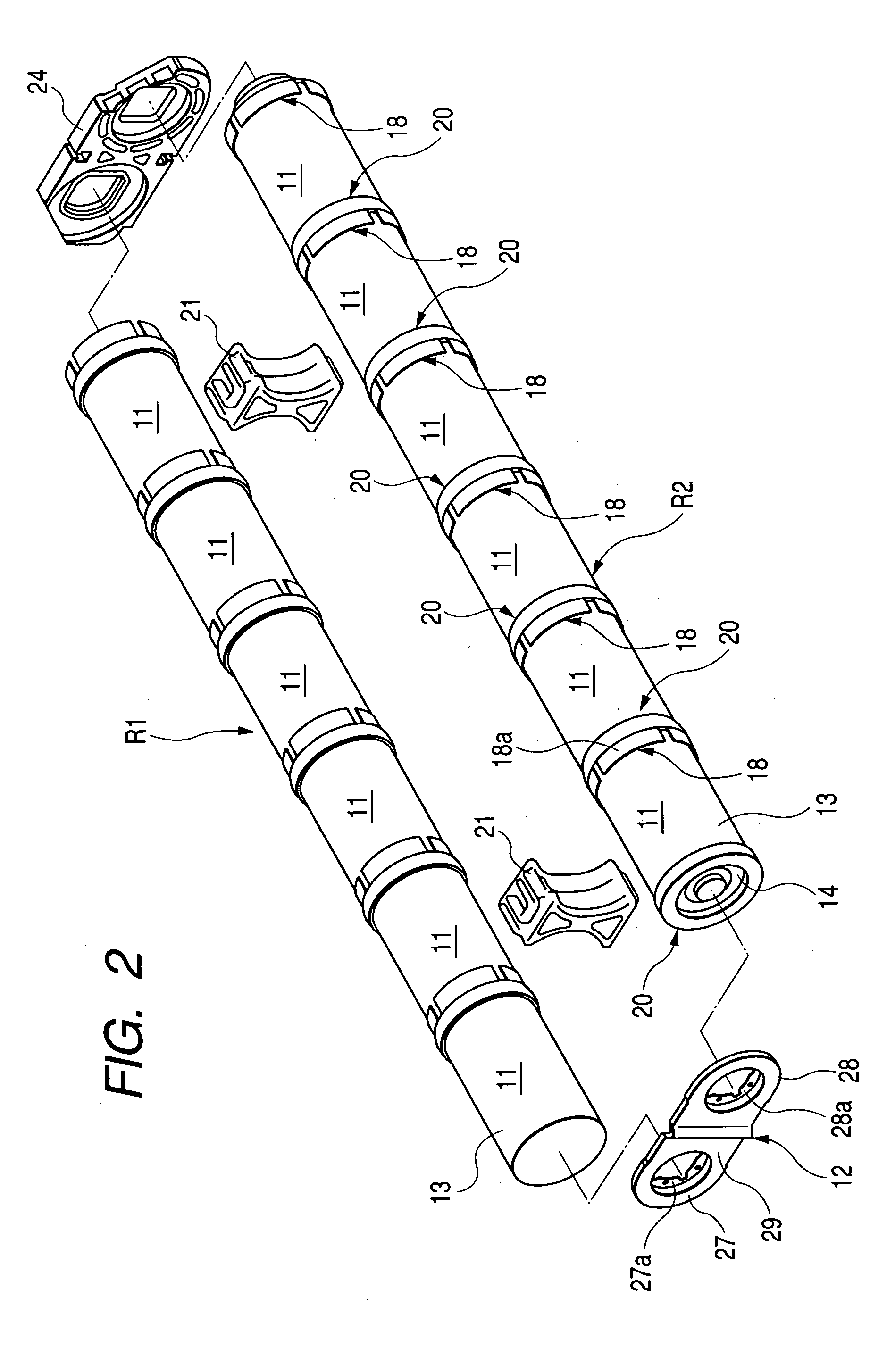
[0042] FIGS. 1 to 6 illustrate the present invention. FIG. 1 is a perspective view of an electric cell module. FIG. 2 is an exploded perspective view of the electric cell module. FIG. 3 is an exploded perspective view of the electric cell module when viewed in the direction opposite to that in which the electric cell module is viewed in FIG. 2. FIG. 4 is a cross-sectional view showing a part of the electric cell module along line 4-4 shown in FIG. 1. FIG. 5 is a front view of a connecting bus bar when viewed from the direction of arrow 5 in FIG. 4. FIG. 6 is a cross-sectional view taken along line 6-6 in FIG. 5.

[0043] First, in FIGS. 1 to 3, this electric cell module is configured while first and second electric cell rows R1, R2, which are connected in parallel to each other, are connected in series by way of a connecting bus bar 12, wherein each of the cell rows R1, R2 is formed by connecting a plurality of electric cells 11; e.g., six electric cells 11, 11, . . . , in series to ea...

third embodiment

[0077]FIGS. 12 and 13 illustrate the present invention. FIG. 12 is a front view of a connecting ring 25 corresponding to FIG. 10. FIG. 13 is a cross-sectional view taken along line 7-7 of FIG. 12.

[0078] The connecting ring 25 integrally includes a large-diameter short cylindrical section 25a, a first flange section 25b, a small-diameter short cylindrical section 25c, and a second flange section 25d. The large-diameter short cylinder section 25a is shaped into a cylinder having one open end, and is fitted over and welded to a surface of an outer periphery of the bottomed cylinder 13 (see the first embodiment). The first flange section 25b extends radially inward from the other end of the large-diameter short cylindrical section 25a and comes into close contact with an outer surface of a closed end of the bottomed cylinder 13. The small-diameter short cylindrical section 25c having one open end is connected to an inner periphery of the first flange section 25b, extends in the directio...

second embodiment

[0080] The connecting ring 25 exclusive of the weld sections 25a . . . of the large-diameter short cylindrical section 25a and the weld sections 25da . . . of the second flange section 25d is set to be equal in wall thickness or greater in wall thickness than the thicker one of the weld sections 25aa . . . and the weld sections 25da . . . . More specifically, in the second embodiment, the wall thickness B2′ of the weld sections 25da . . . of the second flange section 25d is equal to the wall thickness B1′ of the weld sections 25aa . . . of the large-diameter short cylindrical section 25a. Therefore, the wall thickness of the connecting ring 25 exclusive of the weld sections 25aa . . . and 25da . . . is set to be equal to or greater than the thickness B1′ of the weld sections 25aa . . . and the wall thickness B2′ of the weld sections 25da . . . .

[0081] Accordingly, a wall thickness C′ of the first flange section 25b and the small-diameter short cylindrical section 25c of the connecti...


PUM

PropertyMeasurementUnit
thicknessaaaaaaaaaa
thicknessaaaaaaaaaa
thicknessaaaaaaaaaa

Abstract

A connecting bus bar 12 is formed from a negative opposing section 27 which is smaller in thickness than a closed end of a bottomed cylinder 13, partially has a negative weld plate section 27a to be welded to the closed end of a bottomed cylinder 13, and opposes the closed end of the bottomed cylinder 13; a positive opposing section 28 which is smaller in thickness than a seal plate 14, partially has a positive weld plate section 28a to be welded to the seal plate 14, and opposes the seal plates 14; and the coupling section 29 for connecting together the negative opposing section 27 and the positive opposing section 28. The connecting bus bar 12 is formed such that the connecting bus bar 12, which excludes the negative weld plate section 27a and the positive weld plate section 28a, becomes lower in thickness than a thinner one of the closed end of the bottomed cylinder 13 and the seal plate 14.

Description

[0001] This application claims foreign priorities based on Japanese Patent applications No. 2003-322723 and No. 2003-326170, filed Sep. 16, 2003 and Sep. 18, 2003, respectively, the contents of which are incorporated herein by reference in their entirety. BACKGROUND OF THE INVENTION [0002] 1. Field of the Invention [0003] The present invention relates to a structure for connecting electric cells (often referred to as an “electric-cell connecting structure”), and more particularly to an improvement in a structure for connecting electric cells, wherein a pair of electric cells, each having a bottomed cylinder of a negative electrode and a seal plate of a positive electrode attached to an open end portion of the bottomed cylinder in such a manner as to seal the open end of the bottomed cylinder, are connected together by way of a connecting bus bar to be welded to a closed end of the bottomed cylinder and to the other seal plates of both electric cells, or by way of a connecting ring. ...

Claims


Application Information

Patent Timeline
Patent Type & Authority Applications(United States)
IPC IPC(8): H01M50/503H01M50/51H01M50/516H01R24/00H01R33/00
CPCH01M2/204Y02E60/10H01M50/516H01M50/51H01M50/503
Inventor MITA, YOSHINORIANDO, KAZUO
Owner HONDA MOTOR CO LTD
Why Eureka
Try Eureka