Dynamically generated schema representing multiple hierarchies of inter-object relationships

a dynamically generated schema and inter-object relationship technology, applied in the field of object-to-object or “ inter-object relationship” relationships, can solve the problems of complex inter-object relationship (e.g., multiple hierarchy, representing, etc.) that cannot be simply and adequately represented and the elastic data relationship is not easily described, represented or navigated using conventional data store systems and techniques

Inactive Publication Date: 2005-03-31
MICROSOFT TECH LICENSING LLC
View PDF17 Cites 34 Cited by
  • Summary
  • Abstract
  • Description
  • Claims
  • Application Information

AI Technical Summary

Benefits of technology

Systems and methods for dynamically generating a schema representing multiple hierarchies of inter-object relationships are described. In one aspect, a polyarchical query language data structure includes first, second, and third data fields. The first data field is to specify a particular schema for presenting or managing a plurality of objects in a da

Problems solved by technology

Unfortunately, even though a data store can be configured to some extent by a network administrator to represent inter-object relationships within hierarchies of other data, complex inter-object relationships (e.g., such as those representing a single object within more than one hierarchy) are not simply and adequately represented using conventional data store (e.g., directory, database, etc.) systems and technologies.
To make matters worse, elastic data relationships are not easily described, represented, or navigated using conventional data store systems and techniques.
Information about the router and the router modules are typically stored in a directory in one or two different fashions—each of which may be equally unsatisfactory depending on how entities and their respective relationships to other entities are represented.
In consideration of the first design choice, depending how the router and the modules are configured, collapsing information about the router modules, or boards onto the backplane may prove unwieldy.
Whereas considering the second design choice, completely separating the boards from the backplane may be equally unsatisfactory because the router is still a single physical router box that generally includes a number of router modules.
Both of the described solutions to represe

Method used


Image

  • Dynamically generated schema representing multiple hierarchies of inter-object relationships
  • Dynamically generated schema representing multiple hierarchies of inter-object relationships
  • Dynamically generated schema representing multiple hierarchies of inter-object relationships

Examples


Embodiment Construction

Overview

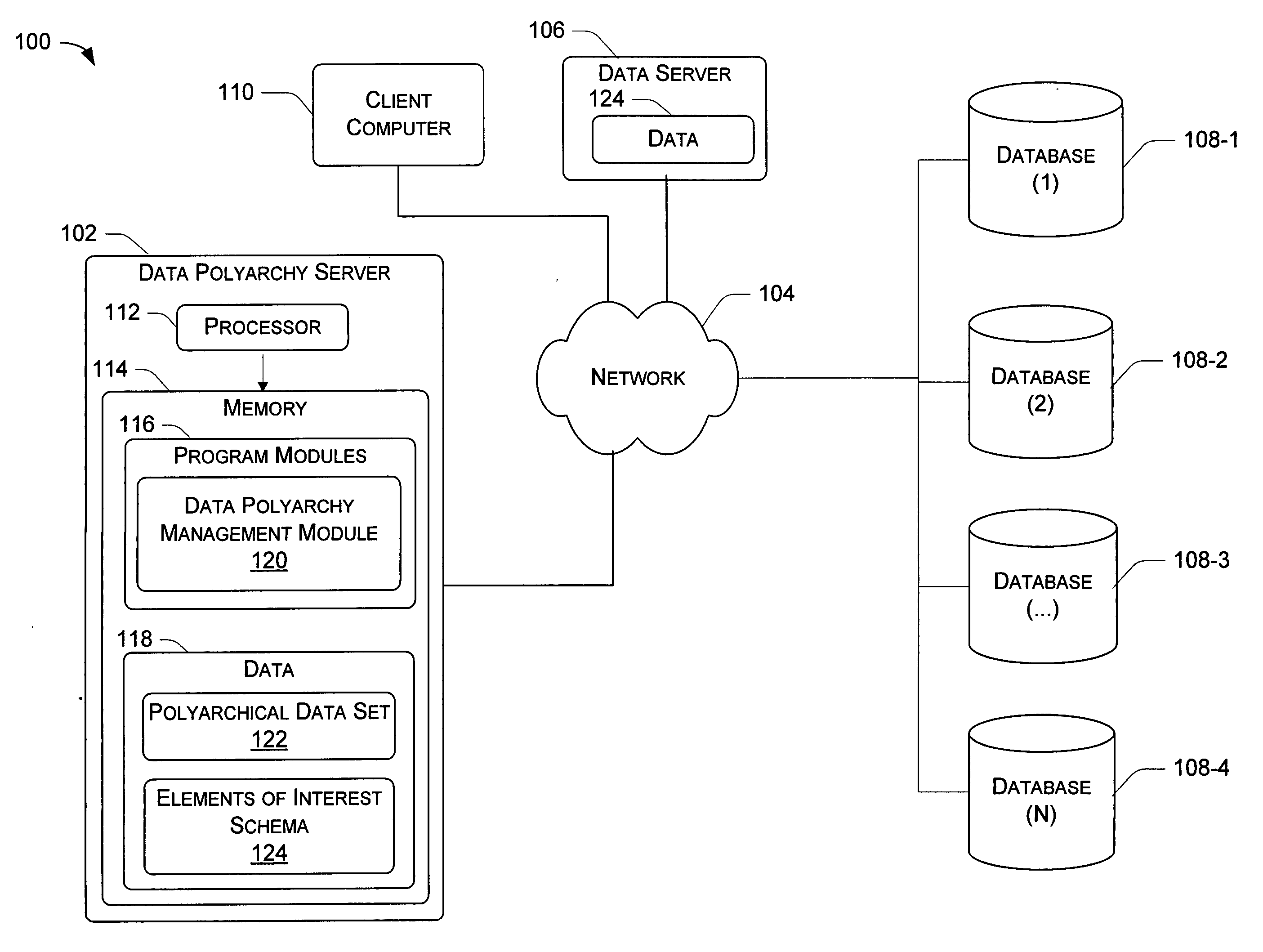
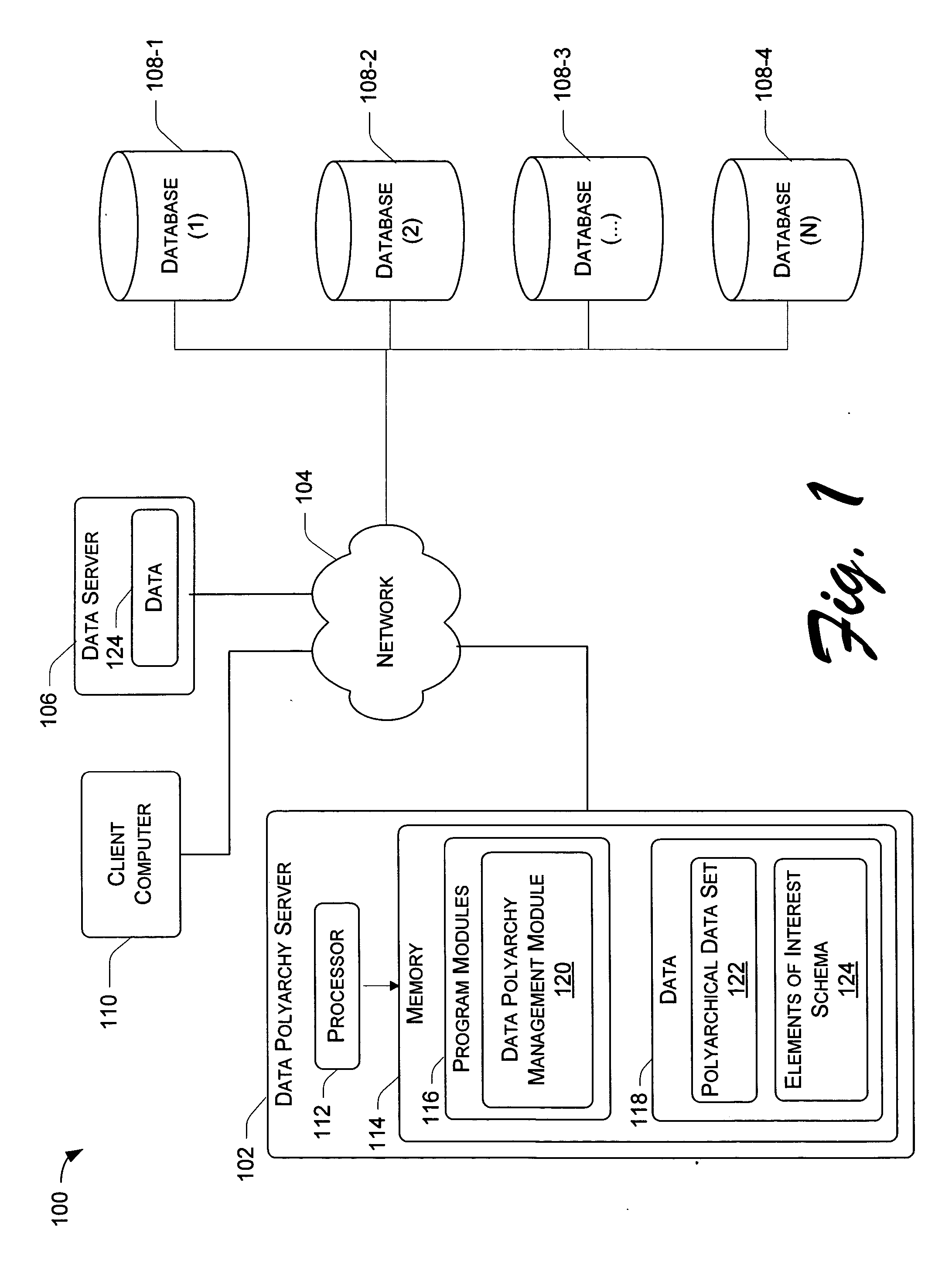
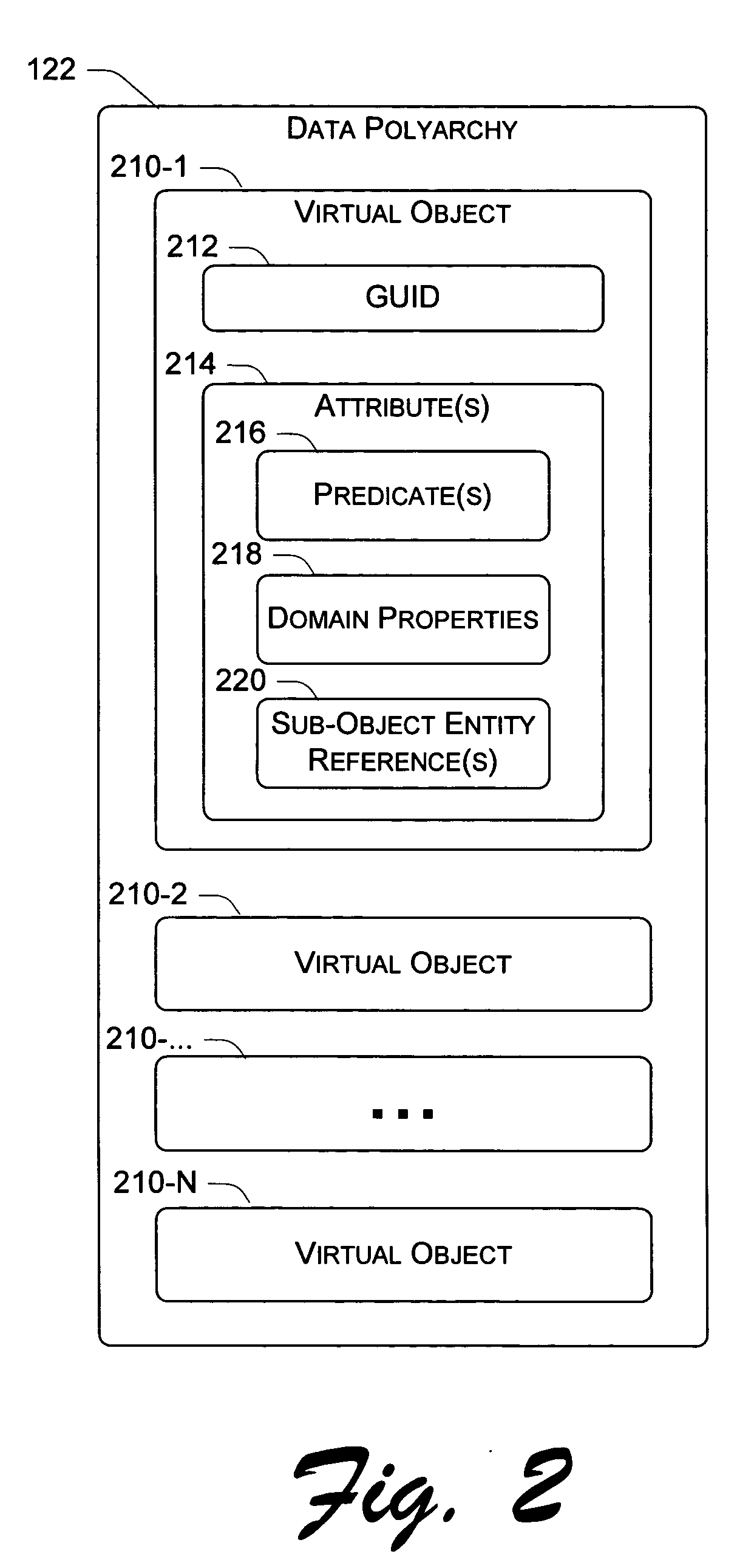
The following subject matter replaces traditional notions of complex real-world object presentation within a single static hierarchy, wherein directory object naming and inter-object relationships are inter-tangled and unwieldy for representing complex data relationships. More specifically, traditional notions of distinguished names for representing inter-object relationships within a single directory of static inter-object relationships are replaced with graphs of elastic (non-static) inter-object connections in multiple dimensions of data relationships (e.g., mono and / or bi-directional relationships) based on attributes of the objects. In other words, the data relationships establish that one or more data objects participate in one or more respective dimensions, or polyarchies of inter-object relationships. One or more of these hierarchies can intersect creating intersecting hierarchies of inter-object relationships.

Dynamically generated multiple hierarchies of data r...


PUM


Abstract

Systems and methods for dynamically generating a schema representing multiple hierarchies of inter-object relationships are described. In one aspect, a polyarchical query language data structure includes first, second, and third data fields. The first data field is used to specify a particular schema for presenting or managing a plurality of objects in a data polyarchy based on values of attributes in the objects. The second data field is to indicate an attribute of interest. The third data field indicates how one or more objects that include the attribute of interest are to be presented or managed with respect to one or more participating dimensions of inter-object relationships based on the schema.

Description

TECHNICAL FIELD The following subject matter relates to object-to-object or “inter-object” relationships. More particularly, the subject matter pertains to interfacing with dynamically generated multiple hierarchies of inter-object relationships based on the values of attributes of the objects. BACKGROUND Any object can be linked, correlated, associated, differentiated, or in some manner categorized with respect to a different object to form implicit or explicit inter-object relationships. For instance, in an organization, a person typically has implicit and explicit relationships with other people in the organization, organizational resources (e.g., printers, facilities, etc.), geographical locations, business units, club memberships, and so on. Each implicit and / or explicit relationship between respective objects (i.e., the person, the other people, a resource, etc.) represents a respective hierarchical data relationship. For example, one hierarchical data relationship is repre...

Claims


Application Information

Patent Timeline
IPC IPC(8): G06F7/00G06F17/00
CPCG06F17/30911Y10S707/99931Y10S707/99943Y10S707/99932Y10S707/99935Y10S707/99947Y10S707/99934Y10S707/99945Y10S707/99944Y10S707/956Y10S707/99933G06F16/81
Inventor CAMERON, KIMMACLEOD, STEWART P.ROBERTSON, GEORGE G.BOOTH, JAMES H.CLEMENT, LUC
Owner MICROSOFT TECH LICENSING LLC
Why Eureka
Try Eureka