Method and adjustable apparatus for masonry wall bracing

a technology of masonry wall bracing and adjustable apparatus, which is applied in the direction of machine supports, building repairs, applications, etc., can solve the problems of destroying walls, putting a burden on mason contractors, endangering craftsmen in the masonry trade, etc., and achieves convenient folding of these members, reducing the death or injury of workers resulting from inadequate prior art bracing, and convenient portability in sections

Inactive Publication Date: 2005-04-07
HODSDON EDWIN R +1
View PDF17 Cites 33 Cited by
  • Summary
  • Abstract
  • Description
  • Claims
  • Application Information

AI Technical Summary

Benefits of technology

[0036] The various shortcomings of these and other prior art approaches are overcome by our invention. Indeed, costing out a masonry job based upon prior art supporting techniques is several times higher than when our new and novel bracing system is employed. Additionally, and perhaps most important, is that worker deaths or injuries resulting from inadequate prior art bracing will be markedly reduced.

Problems solved by technology

From a standards point of view, construction of masonry walls places a burden on the mason contractor to support any masonry wall under fabrication that is over eight feet in height.
Otherwise, without adequate bracing, such winds will readily blow down a wall and endanger craftsman in the masonry trades.
It is not unknown for workmen to be killed or seriously injured when walls are not adequately braced.
Any wall that has not yet been “cured” sufficiently is at risk unless it is adequately and safely braced.
Indeed, such wall destruction happens in spite of the various prior art attempts to use strengthening members and prior art bracing sections as are commonly found in wall construction.
This wooden bracing is not at all acceptable.
Such bracing is subject to cyclic loading from the wind forces and tends to become seriously weakened.
Indeed, it is felt by some that this jumbled wooden approach of the prior art creates other serious safety hazards.
some that this jumbled wooden approach of the prior art creates other serious safety hazards.
In short summary, this wooden timber jumble itself poses saf

Method used


Image

  • Method and adjustable apparatus for masonry wall bracing
  • Method and adjustable apparatus for masonry wall bracing
  • Method and adjustable apparatus for masonry wall bracing

Examples


Embodiment Construction

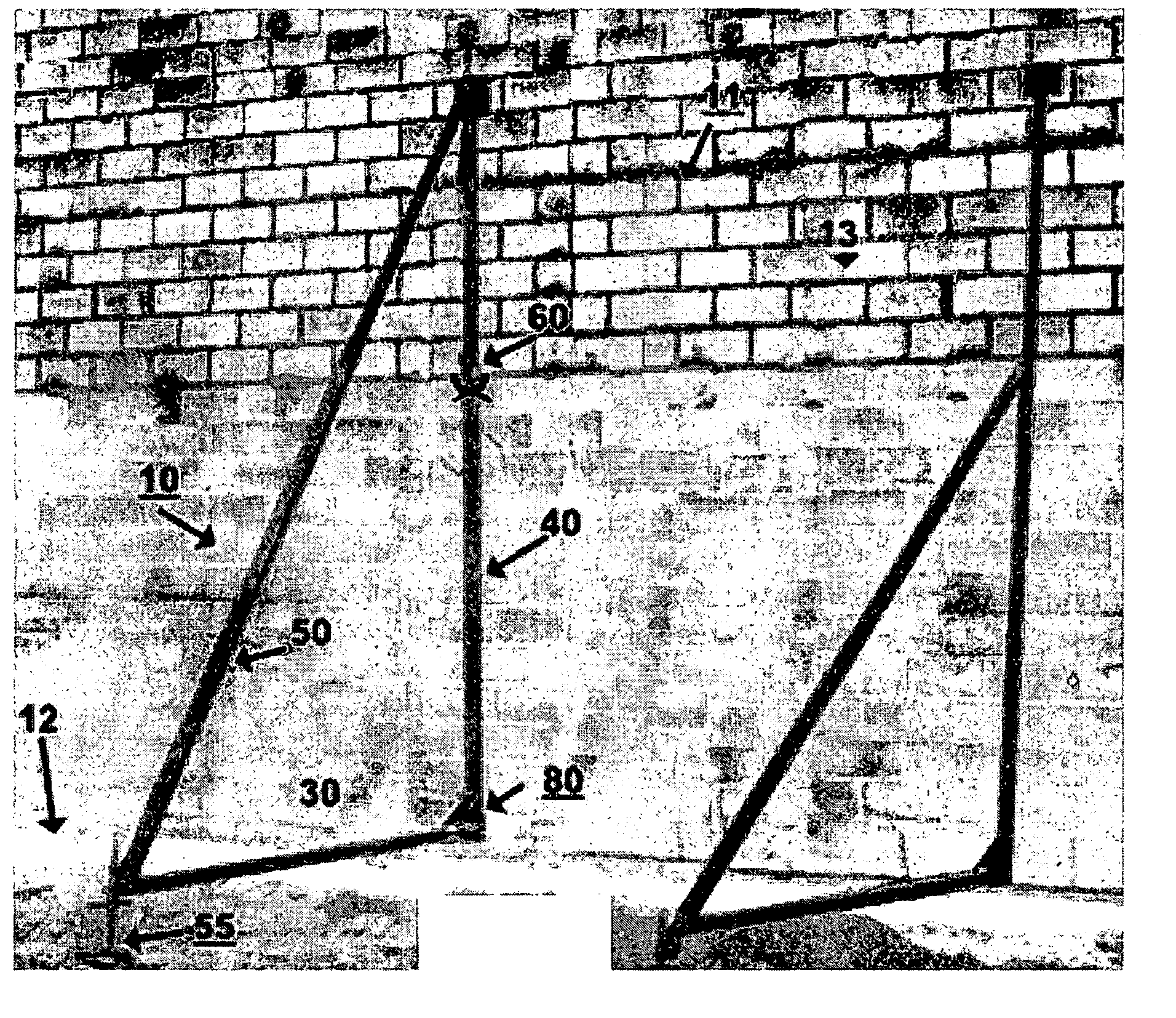
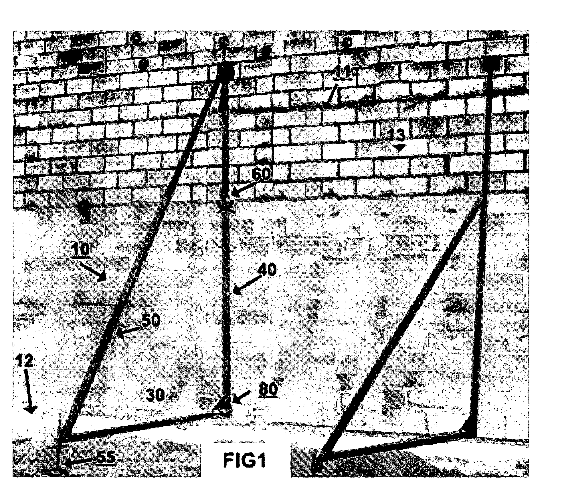
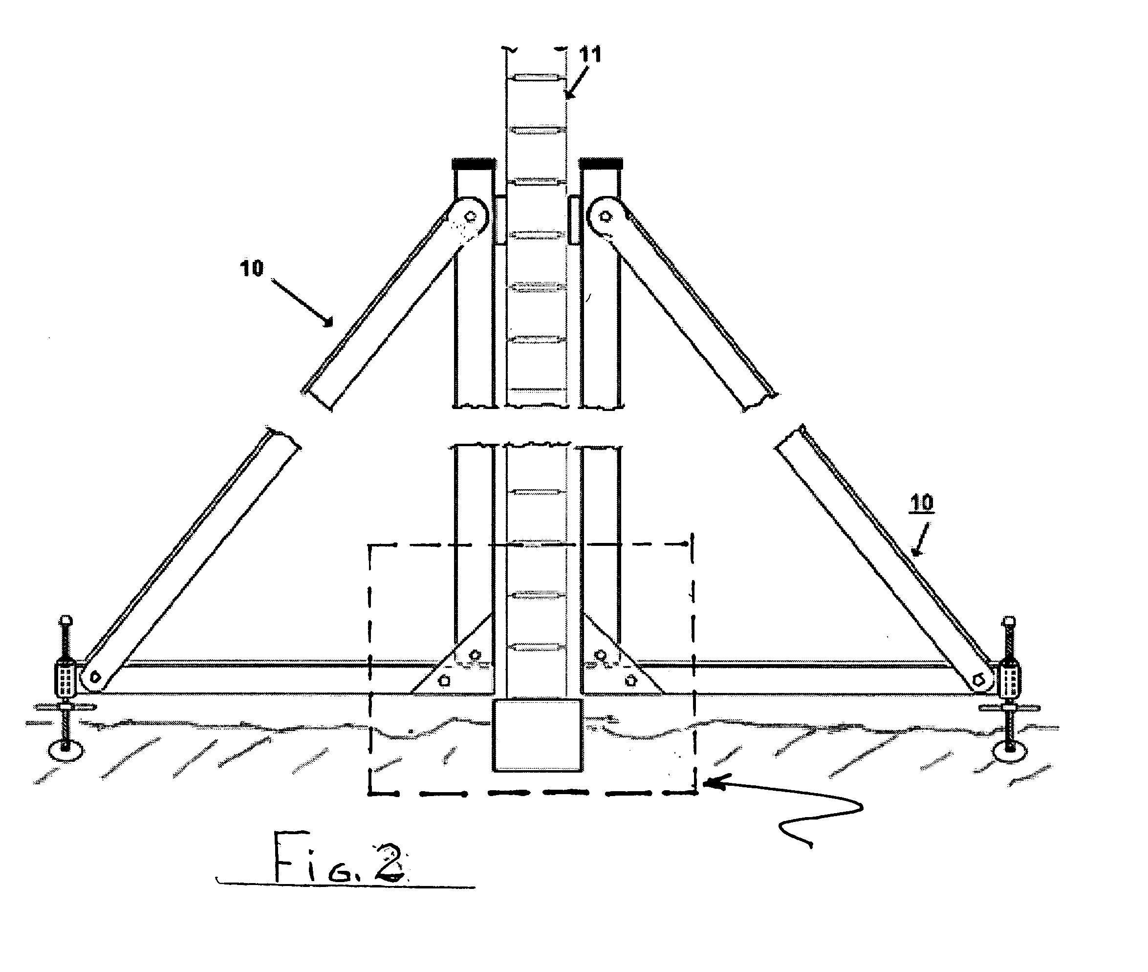
[0058]FIGS. 1 and 2 are views helpful in fully understanding our bracing invention. Each brace 10 as shown is a unitary right angle brace, preferably formed from sturdy square tube steel members, which members are bolted, welded or otherwise assembled into a unitary right angle brace structure 10. A brace 10 is moved on site in separated member fashion and may be assembled while leaning on the ground. And then, the assembled frames is manually rotated (See FIG. 3) and held upright level and flush as will become clearer from the additional description of the invention.

[0059] While primarily intended to be employed in opposing pairs (See FIG. 2) our invention may, in a particular case, consist of a single right angle brace 10 held flush against a wall by adjustable connecting and leveling means (80 and 55, FIG. 1, respectively). Most often, however, our preferred embodiment is as shown in FIG. 2 depicting a pair of braces 10a and 10b, in back-to-back upright position aligned and held...


PUM


Abstract

Adjustable apparatus for bracing one or both sides of a wall being fabricated from masonry blocks and having an opening near the base of the block wall. Bracing system includes strong rigid members assembled in the form of a right angle brace set having stiff vertical, horizontal and diagonal members, a connector having a length sufficient to extend through the opening affixed at a right angle location of one or both of the brace sets. A pair of such braces—back to back, and spaced on opposite sides of a wall—are interconnected together via this connector. Selected brace members telescope to accommodate increases in wall height and a manually adjustable outrigger screwjack at the remote end of the horizontal member eliminates reliance on prior art deadmen.

Description

[0001] On Sep. 20, 2003 the United States Patent Office received a copy of—and assigned Ser. No. 60 / 503,976 to—a Provisional Patent Application (PPA) filed by the same inventors hereof. That PPA is incorporated herein by this reference as though set out here in full. Additionally, the PPA is being supplemented by this Regular Patent Application (RPA). Applicant expressly reserves all rights and privileges flowing from the PPA and its earlier official filing date and contents thereof. This RPA follows, and it is supported by the PPA.BACKGROUND OF THE INVENTION [0002] 1. Field of the Invention [0003] This invention relates to masonry wall bracing and bracing systems for such wall. More specifically, the field of this invention relates to adjustable bracing anchored at a self-supporting base for safely assuring the construction of masonry walls. Additionally the field of this invention relates to a bracing system that sandwiches both sides of a wall under construction by a “connected-t...

Claims


Application Information

Patent Timeline
IPC IPC(8): E04G21/26E04G23/04
CPCE04G23/04E04G21/26
Inventor HODSDON, EDWIN R.GRENIER, LAURENT E.
Owner HODSDON EDWIN R
Why Eureka
Try Eureka