
Coupling device

Inactive Publication Date: 2005-04-07
ULTIMATE DESIGN SOLUTIONS
View PDF9 Cites 4 Cited by
  • Summary
  • Abstract
  • Description
  • Claims
  • Application Information

AI Technical Summary

Benefits of technology

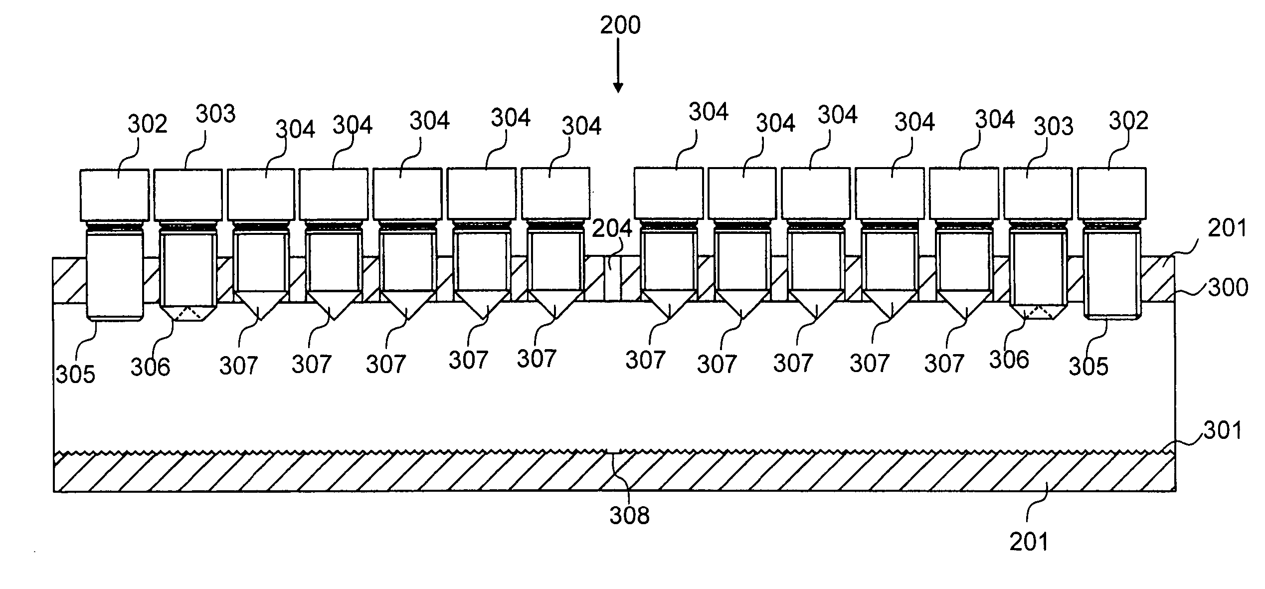
[0010] The inventors, on realizing the disadvantages associated with prior art coupling devices, provide a coupling device for coupling reinforcing bars, wires and cables, comprising, in part, a plurality of engagers being adjustably positioned through a tubular body, where the plurality of engagers are configured with a plurality of different end portions configured for a different engaging of the reinforcing bars. The different end portions may be configured to engage onto an outer surface of the reinforcing bars, to engage partially into the reinforcing bars and / or an engaging into the reinforcing bars providing, in turn, a range of reduced bar cross-sectional areas as a consequence of the amount of engager penetration. The amount of load transfer from bar to coupling device, via indirectly the different engagers, is also dependent upon the nature of the engager end portion. For example, the coupling device at a region having an engager configured for, substantially, non-penetration, engagers onto the bars, such that the device experiences a reduced amount of load transfer as compared to a region having an engager configured for bar penetration and an engaging into the reinforcing bars. Through the provision and positioning of a plurality of engagers configured with a plurality of different end portions extending longitudinally along the tubular body of the coupling device, bar breakage within the region of the coupling device is avoided up to and including the ultimate tensile strength of the reinforcing bars.
[0032] As such, due to the nature and relative positioning of the plurality of engagers configured with a plurality of different end portions, the amount of load transfer from reinforcing bars to coupling device is more uniform along the length of the device compared to that found in the art. Accordingly, a coupling device is described herein which avoids bar breakage within the region of the coupling device being achieved by controlled engager-bar penetration along the length of the reinforcing bars such that at any point along the reinforcing bars within the coupling device, the cross-sectional area of the bars is not reduced to an extent where load transfer from bar to coupler body is not achieved.
[0036] According to a further aspect of the present invention the coupling device comprises at least one face extending longitudinally on an inner surface of the tubular body and at least one recessed gripping surface being formed on the at least one face and extending longitudinally on at least one face wherein the at least one recessed gripping surface is configured to grip the reinforcing bars in response to an engaging of the reinforcing bars by the plurality of engagers. The provision of at least one recessed gripping surface allows the reinforcing bars to be seated correctly within the coupling device and serves to provide an extended area of contact between coupler and the reinforcing bars.

Problems solved by technology

In particular, settable materials found in the art comprise low fire resistance introducing, in turn, safety concerns.
Cementitious grout has been employed to overcome the problem of using low fire resistance material, however this in turn creates additional problems.
As a result of the grout having high viscosity, air pockets or voids within the coupling region are observed resulting in a weak joint.
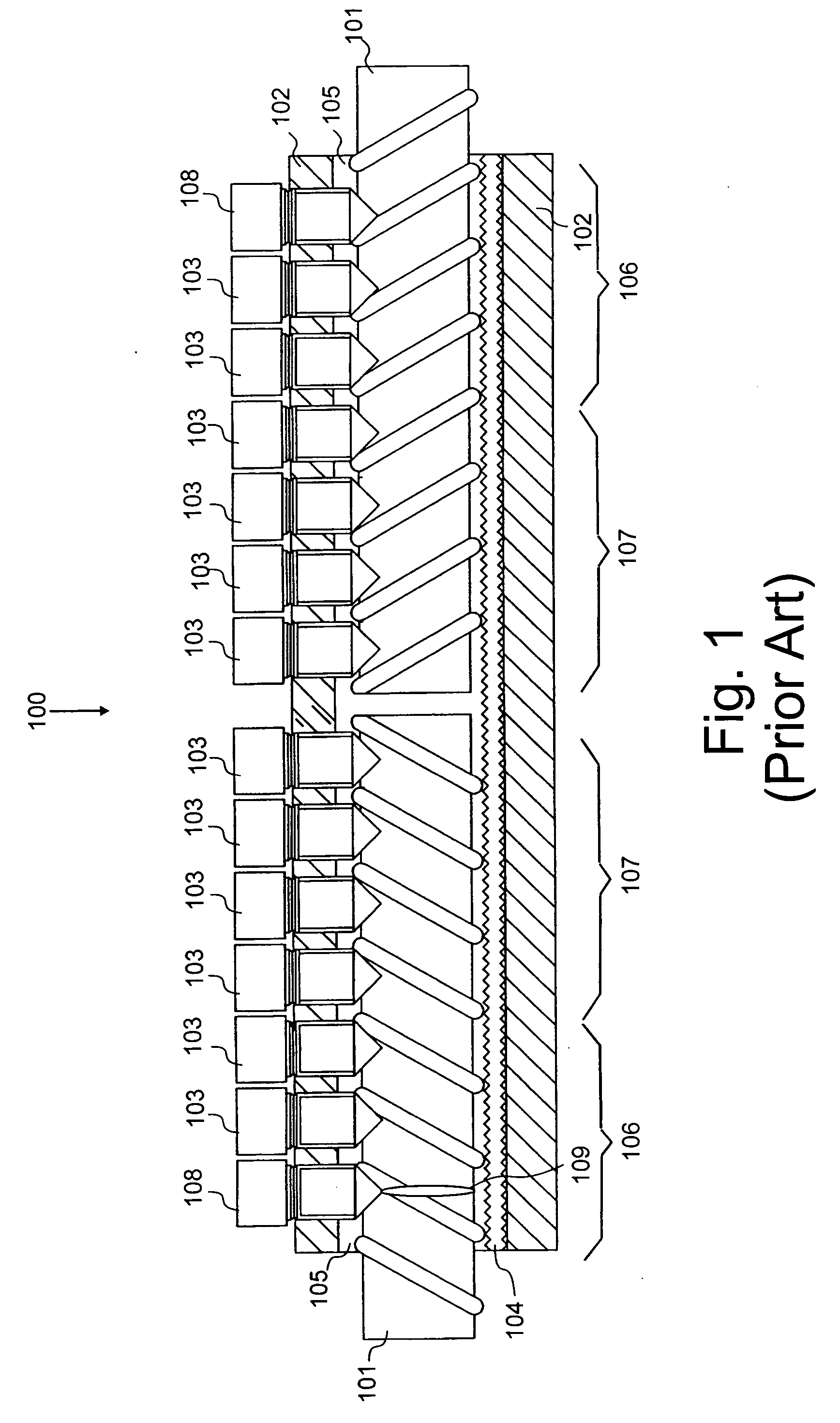
Accordingly, the inventors have realized various disadvantages associated with prior art coupling devices involving a plurality of engagers configured to engage into the reinforcing bars thereby performing a wedging action.
Consequently, the region of coupling of reinforcing bars using coupling devices found in the art, reduces the maximum loading force tolerance of the bars used in structural concrete.
Moreover, bar breakage within the region of the coupler body even at nominal ultimate tensile strength of the bar is considered by some regulatory authorities as failure of the coupler.

Method used


Image

  • Coupling device
  • Coupling device
  • Coupling device

Examples


Embodiment Construction

[0137] There will now be described by way of example the best mode contemplated by the inventors for carrying out the invention. In the following description numerous specific details are set forth in order to provide a thorough understanding of the present invention. It will be apparent however, to one skilled in the art, that the present invention may be practiced without limitation to these specific details. In other instances, well known methods and structures have not been described in detail so as not to unnecessarily obscure the present invention.

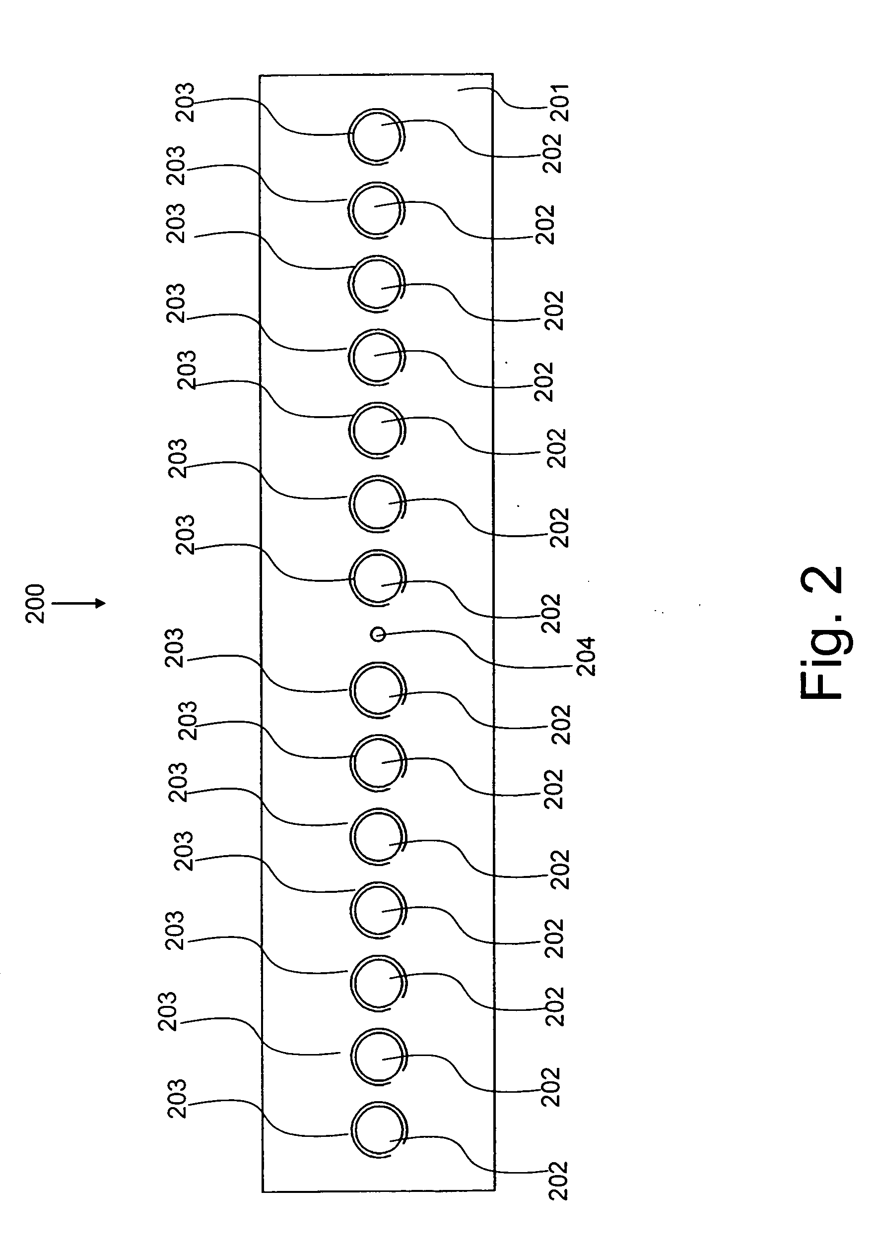
[0138] Referring to FIG. 2 herein there is illustrated a plan view of the bar coupling device according to the specific implementation of the present invention. The coupling device 200 comprises an elongate tubular body 201, a plurality of longitudinally spaced holes 202 and a centrally located hole 204, according to the specific implementation of the present invention. The elongate tubular body 201 is manufactured from a steel or s...


PUM


Abstract

A coupling device for coupling reinforcing bars used in structural concrete comprising an elongate tubular body for receiving bar end portions, a plurality of engagers being adjustably positioned through the elongate tubular body, the coupling device being characterized in that the plurality of engagers are configured with a plurality of different end portions being configured for a different engaging of the reinforcing bars.

Description

FIELD OF THE INVENTION [0001] The present invention relates to the coupling of bars, wires and cables, in particular but not exclusively, to the coupling of reinforcing bars used in structural concrete. BACKGROUND TO THE INVENTION [0002] There exists within the art, apparatus and method for coupling reinforcing bars used in structural concrete, such coupling commonly involving the use of a tubular steel coupling body or sleeve configured to receive end portions of the reinforcing bars. Typically, the bars are held in place within the coupling body using a number of engagers, these being for example, bolts or screws which engage into the reinforcing bars thereby wedging the bars against an inner surface of the tubular body providing the couple. [0003] Typical coupling devices found in the art generally comprise engagers having pointed end portions to achieve an engaging into the reinforcing bars and not an engaging onto an outer surface of the bars thereby providing established conta...

Claims


Application Information

Patent Timeline
IPC IPC(8): E04C5/16F16B7/04
CPCE04C5/165Y10T403/551Y10T403/5733F16B7/0426
Inventor HOPWOOD, IAN
Owner ULTIMATE DESIGN SOLUTIONS
Learn More