Mounting assembly for igniter in a gas turbine engine combustor having a ceramic matrix composite liner

a technology of ceramic matrix and combustor, which is applied in the direction of machines/engines, burner ignition devices, lighting and heating apparatus, etc., can solve the problems of shortening the life cycle of components, difficult substitution of materials having higher temperature capabilities than metals, and the inability to utilize igniter ferrules with cmc lines

Inactive Publication Date: 2005-04-07
GENERAL ELECTRIC CO
View PDF18 Cites 36 Cited by
  • Summary
  • Abstract
  • Description
  • Claims
  • Application Information

AI Technical Summary

Problems solved by technology

As explained in U.S. Pat. No. 6,397,603 to Edmondson et al., substitution of materials having higher temperature capabilities than metals has been difficult in light of the widely disparate coefficients of thermal expansion when different materials are used in adjacent components of the combustor.
This can result in a shortening of the life cycle of the components due to thermally induced stresses, particularly when there are rapid temperature fluctuations which can also result in thermal shock.
It will be appreciated that such an igniter ferrule cannot be utilized with the CMC liner because there is no way to weld or otherwise attach the metal ferrule thereto.
Further the igniter hole required in the outer liner to accommodate relative axial movement between the CMC liner and the combustor casing cannot be left open because the combustor likely will be unable to light.

Method used


Image

  • Mounting assembly for igniter in a gas turbine engine combustor having a ceramic matrix composite liner
  • Mounting assembly for igniter in a gas turbine engine combustor having a ceramic matrix composite liner
  • Mounting assembly for igniter in a gas turbine engine combustor having a ceramic matrix composite liner

Examples


Embodiment Construction

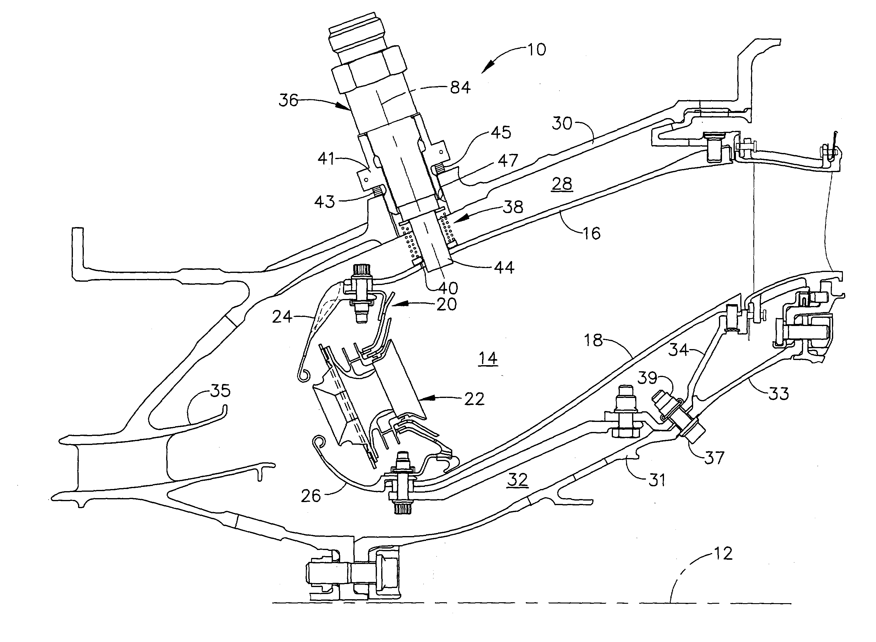
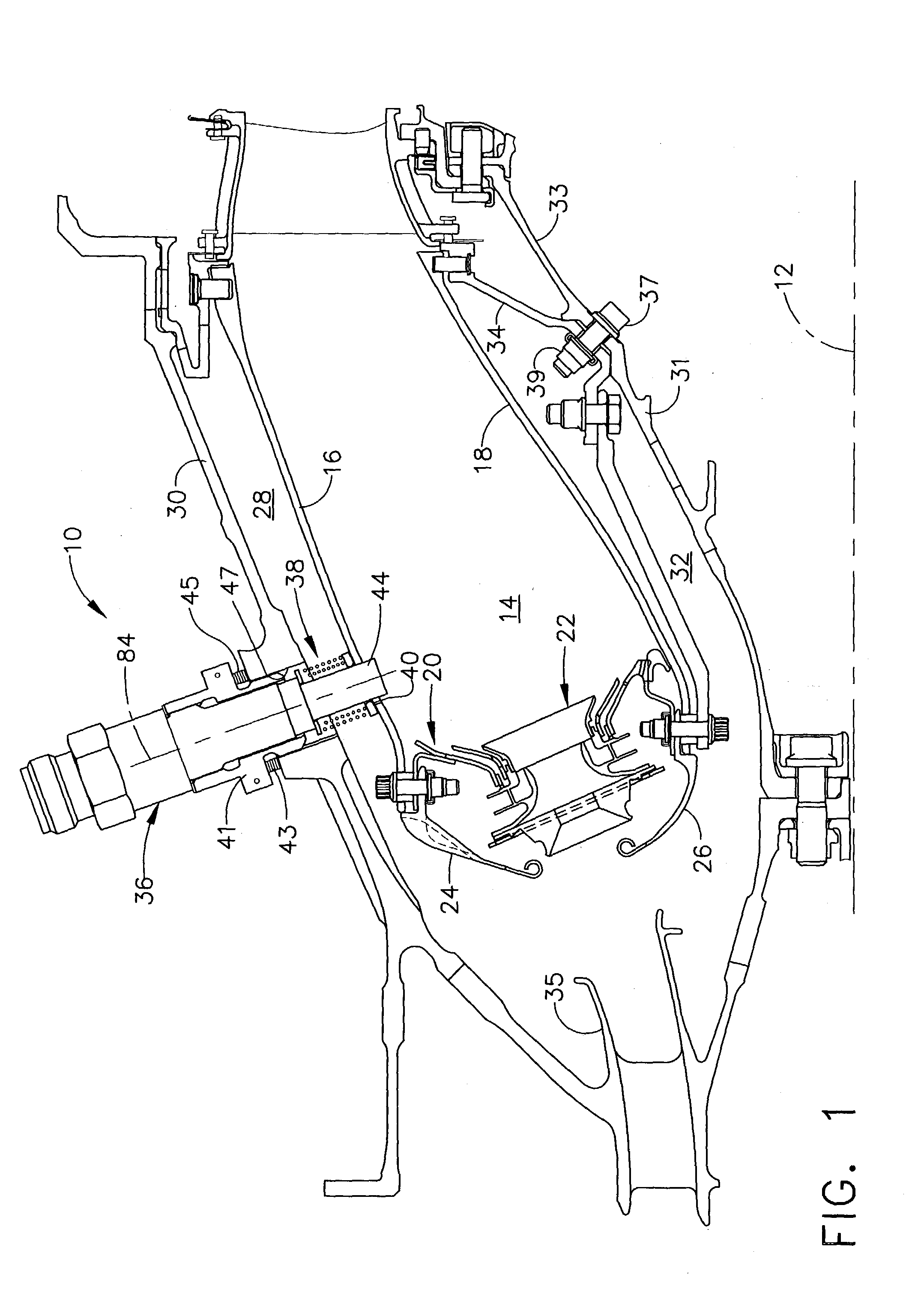
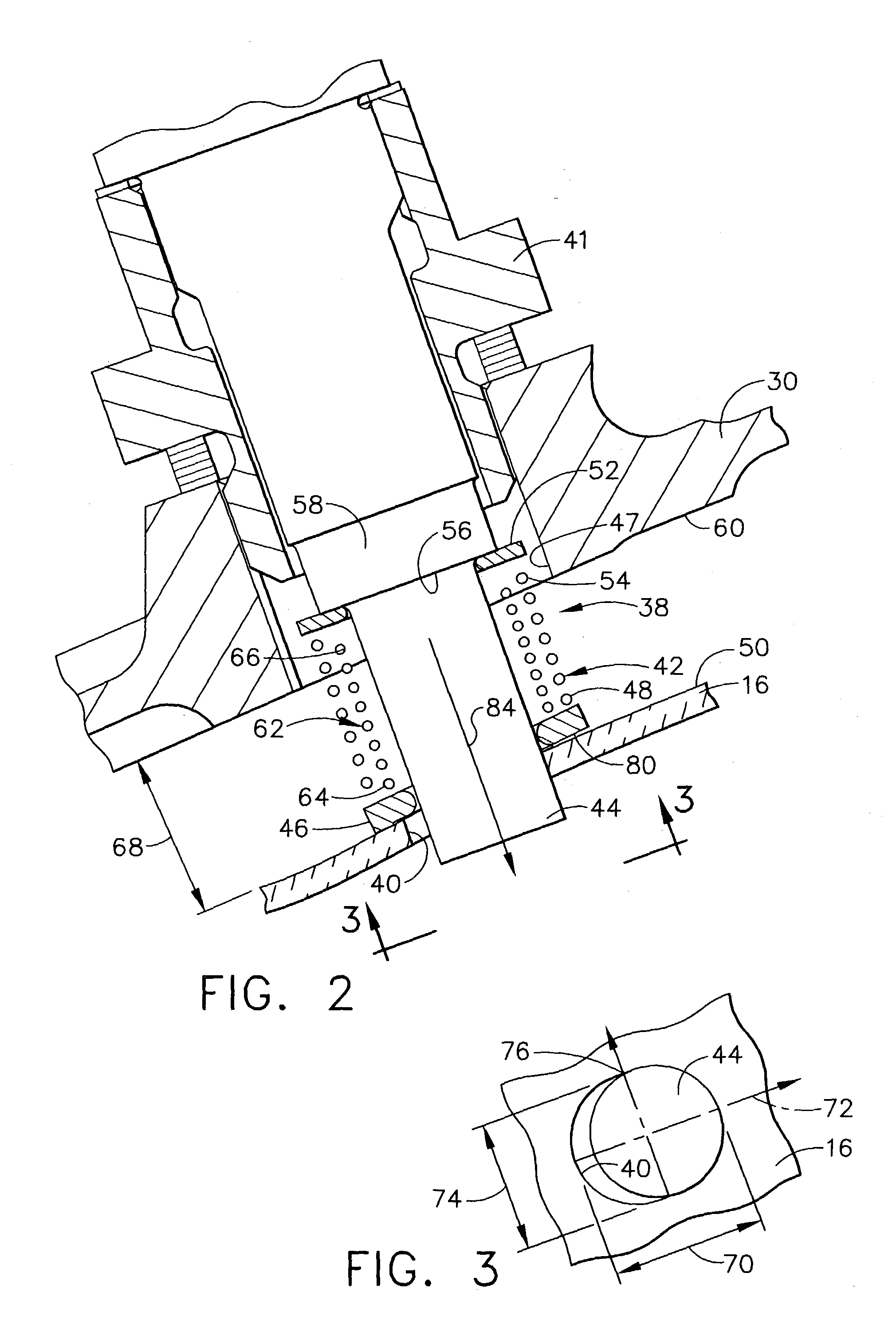
[0019] Referring now to the drawings in detail, wherein identical numerals indicate the same elements throughout the figures, FIG. 1 depicts an exemplary gas turbine engine combustor 10 which conventionally generates combustion gases that are discharged therefrom and channeled to one or more pressure turbines. Such turbine(s) drive one or more pressure compressors upstream of combustor 10 through suitable shaft(s). A longitudinal or axial centerline axis 12 is provided through the gas turbine engine for reference purposes.

[0020] It will be seen that combustor 10 further includes a combustion chamber 14 defined by an outer liner 16, an inner liner 18 and a dome 20. Combustor dome 20 is shown as being single annular in design so that a single circumferential row of fuel / air mixers 22 are provided within openings formed in such dome 20, although a multiple annular dome may be utilized. A fuel nozzle (not shown) provides fuel to fuel / air mixers 22 in accordance with desired performance...


PUM


Abstract

An assembly for mounting an igniter in a gas turbine engine combustor between an outer casing and an outer liner, wherein a longitudinal centerline axis extends through the gas turbine engine. The igniter mounting assembly includes a first spring member encircling a portion of said igniter and being positioned between a surface adjacent the outer casing and an outer surface of the outer liner, a first ring member connected to a first end of the first spring member adjacent the outer surface of the outer liner, and a second ring member connected to a second end of the first spring member adjacent the surface adjacent the outer casing. Accordingly, the igniter is able to maintain substantial alignment with respect to an opening in the outer liner while moving radially and/or axially with respect to the outer liner as the outer casing experiences thermal growth greater than the outer liner.

Description

STATEMENT REGARDING FEDERALLY SPONSORED RESEARCH AND DEVELOPMENT [0001] The U.S. Government may have certain rights in this invention pursuant to contract number NAS3-27720.BACKGROUND OF THE INVENTION [0002] The present invention relates generally to the use of Ceramic Matrix Composite liners in a gas turbine engine combustor and, in particular, to the mounting of an igniter between an outer casing and an outer liner of the combustor so as to accommodate differences in thermal growth. [0003] It will be appreciated that the use of non-traditional high temperature materials, such as Ceramic Matrix Composites (CMC), are being studied and utilized as structural components in gas turbine engines. There is particular interest, for example, in making combustor components which are exposed to extreme temperatures from such material in order to improve the operational capability and durability of the engine. As explained in U.S. Pat. No. 6,397,603 to Edmondson et al., substitution of materia...

Claims


Application Information

Patent Timeline
Patent Type & Authority Applications(United States)
IPC IPC(8): F02C7/264F16F3/04F23R3/60
CPCF02C7/264F16F3/04F23R2900/00012F23D2211/00F23R3/60F23D2207/00
Inventor WELLS, THOMAS ALLENBULMAN, DAVID EDWARDNOE, MARK EUGENEHANSEL, HAROLD RAYGLYNN, CHRISTOPHER CHARLES
Owner GENERAL ELECTRIC CO
Why Eureka
Try Eureka