Cup lid apparatus

a technology of lids and cups, applied in the field of plastic lids, can solve the problems of increasing the probability that the contents of the cup will be spilled during the removal process, the design of cup lids using this type of lids is not consumer-friendly, and the contents of the cup cannot be easily enjoyed

Inactive Publication Date: 2005-04-07
MORRIS JEFFREY M +1
View PDF39 Cites 42 Cited by
  • Summary
  • Abstract
  • Description
  • Claims
  • Application Information

AI Technical Summary

Benefits of technology

In accordance with the present invention, these and other problems are overcome by providing a cup lid for a drinking cup containing a liquid, the cup having a base and a sidewall extending upwardly from the base, the sidewall including an inner surface, a top end, and a rim extending along the circumference of the top end. The cup lid comprises a first part lying in a first plane and having a top surface and a center axis, means on the first part for releasably mounting the first part to the top end of the cup to form a substantially liquid tight seal between the cup lid and the cup, a second part depending radially outwardly from the first part and lying in a second plane, the second part having means for movement relative to said first part, compartment means between the cup and the cup lid for bifurcating the liquid in the cup into one portion and a second portion, the one portion comprising means for facilitating the flow of liquid into the compartment means and the second portion for facilitating the flow of liquid out of the compartment means, the first part and the second part further comprise first aperture means for permitting the liquid contained in the one portion to flow out of the compartment means and out of the drinking cup, the second part comprises baffle means for substantially shielding the liquid in the one portion from substantial wave interference with the liquid in the second portion during any lateral movement of the cup whereby any spillage of the liquid out of the cup is substantially minimized.
It is still another further object of the present invention to provide a cup lid which forms two compartments within the cup wherein each compartment contains a liquid and wherein the liquid contained within the channel compartment does not easily spill out of the cup when the cup is at least moved laterally.

Problems solved by technology

However, conventional cup lid designs are not consumer friendly especially when used to drink hot liquids, such as coffee or tea and the like.
The contents of a cup using this type of lid cannot be easily enjoyed, because the entire lid must be removed to drink the contents which is at best cumbersome and at worst, dangerous, especially when the liquid contents of the cup is hot, such as coffee and the like.
A problem with these types of lids is that the section of the lid, which is folded, is very cumbersome to remove thereby increasing the probability that the contents of the cup will be spilled during the removal process.
Also, once the section is removed, the possibility of spillage increases when the cup is suddenly jarred, moved or tilted because the aperture is large to accommodate drinking.
This design feature, however, while minimizing spillage, has the disadvantage of hindering one's ability to comfortably drink the beverage since typically, only a small amount of liquid can be drained from the cup with each sip.
Another disadvantage of the prior art is that the cup lids provide no means for keeping the contents of the cup hot for an extended period of time.

Method used


Image

  • Cup lid apparatus
  • Cup lid apparatus
  • Cup lid apparatus

Examples


second embodiment

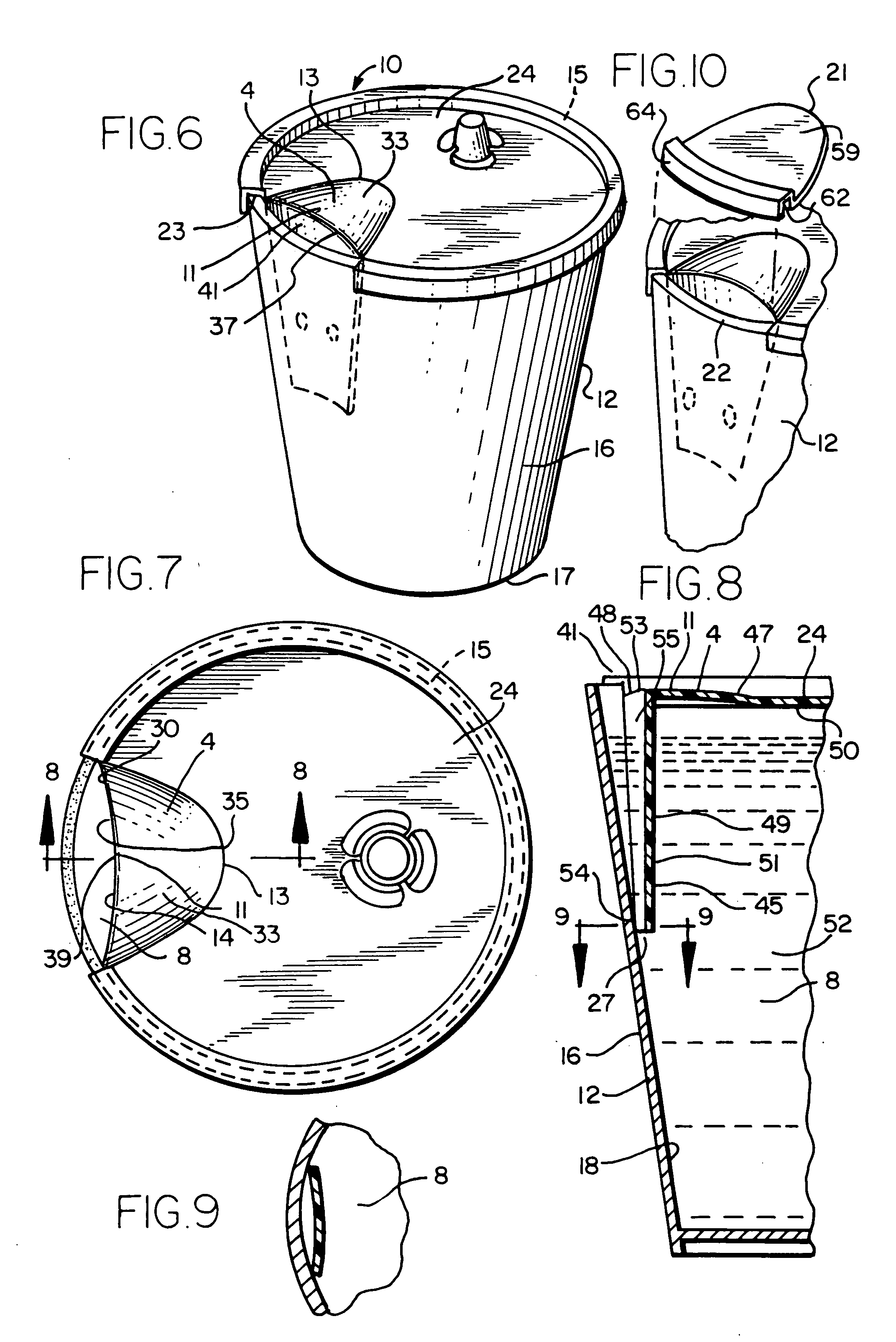
In the present invention shown in FIG. 10, a third part 59 is shown which is hingedly attached to the first part 24 along edge 31 and which is capable of moving from a closed position whereby slotted edge 62 located along the outer perimeter 64 of third part 59 and which is releasably mounted to the rim 22 of cup 12. Third part 59 is positioned substantially over and above first aperture 41 to form a substantially liquid tight seal 15 with rim 22 when in the closed position thereby preventing the egress of liquid 8 from the cup 12. Third part 59 may be easily removed from rim 22 by simply lifting it off the rim 22 and the contents of the cup may then be poured or drunk from the cup 12. Third part 59 may also be removed from cup lid 10 by tearing it off at hinge alone edge 31.

third embodiment

A third embodiment of the present invention is shown in FIG. 11 to FIG. 13. the present invention comprises an insert 9 that is used in combination with conventional cup lid 1. Cup lid 1 comprises a slotted peripheral edge 60 which extends around the perimeter 61 of cup lid 1 and which is releasably mounted to rim 22 in the same manner as the cup lid 10 of the preferred embodiment of the present invention is releasably mounted to the cup rim 22. Lid 1 further comprises a third part 65 which is hingedly attached to the cup lid 1 for movement between a closed position 66 for releasable mounting to the rim 22 of cup 12 to form a liquid tight seal 15 with the slotted edge 60 of lid 1 to cup 12 (FIG. 13) and an open position (not shown) wherein third part 65 is released from its mounted position on rim 22 of cup 12 and may be either left alone to hang on cup lid 1 as a “chad” or may be entirely removed, as shown in FIG. 11 leaving aperture 67.

The insert 9 of the third embodiment of the ...

fourth embodiment

A fourth embodiment of the present invention is shown in FIG. 14 to FIG. 17. the present invention comprises an insert 9 that is used in combination with cup lid 1. Cup lid 1 comprises a slotted peripheral edge 60 which extends around the perimeter 61 of cup lid 1 and which is releasably mounted to rim 22 in the same manner as the cup lid 10 of the preferred embodiment of the present invention is releasably mounted to the cup rim 22. Lid 1 further comprises a third part 65 which is hingedly attached to the cup lid 1 for movement between a closed position 66 (FIG. 17) for releasable mounting to the rim 22 of cup 12 to form a liquid tight seal 15 with the slotted edge 60 of lid 1 and an open position (not shown) wherein third part 65 is released from its mounted position on rim 22 but is left attached as a “chad” to lid 1. In the alternative, third part 65 may be permanently removed from lid 1 by tearing it off lid 1. See, FIG. 14) Substantially below and aligned with third part 65, i...


PUM

PropertyMeasurementUnit
temperatureaaaaaaaaaa
circumferenceaaaaaaaaaa

Abstract

A cup lid for use with a drinking cup containing a liquid, the drinking cup having a base and a sidewall extending upwardly from the base, the sidewall including an inner surface, a top end, and a rim extending along the circumference of the top end. The cup lid comprises a first part lying in a first plane and having a top surface and a center axis, means on said first part for releasably mounting the first part to the top end of the cup to form a substantially liquid tight seal between the cup lid and the cup, a second part depending radially outwardly from the first part and lying in a second plane, the second part having means for movement relative to the first part, compartment means between the cup and the cup lid for bifurcating the liquid in the cup into one portion and a second portion, the one portion comprising means for facilitating the flow of liquid into the compartment means and the second portion for facilitating the flow of liquid out of the compartment means, the first part and the second part further comprise aperture means for permitting the liquid contained in said one portion to flow out of the compartment means and out of the drinking cup. The second part comprises baffle means for substantially shielding the liquid in the one portion from substantial interference with the liquid in the second portion during any lateral movement of the cup whereby any spillage of the liquid out of the cup is substantially minimized.

Description

BACKGROUND OF THE INVENTION The present invention relates to a plastic lid for a drinking cup. In particular, the invention relates to a lid having a flexible flange which depends downwardly into the cup and rests contiguously against the cup's inner sidewall surface to form a channel and two apertures through which the contents of the cup may be emptied. Drinking cups are a ubiquitous product in the beverage industry. It is common to use drinking cups made out of Styrofoam and the like especially for take-out restaurants and convenience stores. It is common practice to use a cup lid with the cups especially when the drinks are carried to present spillage. However, conventional cup lid designs are not consumer friendly especially when used to drink hot liquids, such as coffee or tea and the like. There are many prior art drinking cup lids which come in various permutations. One type of prior art lid acts as a solid cover which is attached to the rim of the cup to prevent the liqui...

Claims


Application Information

Patent Timeline
Patent Type & Authority Applications(United States)
IPC IPC(8): B65D43/02B65D51/24B65D55/00B65D55/02
CPCB65D43/0218B65D51/24B65D55/00B65D55/024B65D2543/00555B65D2543/00046B65D2543/00092B65D2543/00296B65D2543/00509B65D2205/02
Inventor MORRIS, JEFFREY M.WHEELER, DAVID C.
Owner MORRIS JEFFREY M
Why Eureka
Try Eureka