Fuel injection valve

a fuel injection valve and valve body technology, applied in the direction of fuel injecting pumps, valve operating means/release devices, machines/engines, etc., can solve the problems of large size of the electromagnetic means of high performance, deterioration of the mountability of the fuel injection valve on the internal combustion engine, and large size of the fuel injection valve, so as to achieve a large valve opening force and high performance

Inactive Publication Date: 2005-04-07
TOYOTA JIDOSHA KK +1
View PDF7 Cites 8 Cited by
  • Summary
  • Abstract
  • Description
  • Claims
  • Application Information

AI Technical Summary

Benefits of technology

[0013] Generally, the needle of the fuel injection valve, when moved in the direction away from the fuel injection port, is subjected to the force in the direction away from the fuel injection port (valve opening force due to the fuel pressure) by the pressure of the fuel flowing into the forward end of the needle. The valve opening force due to the fuel pressure tends to increase with the degree to which the needles moves away from the fuel injection port. The valve opening force due to the fuel pressure, therefore, assumes a maximum value when the needle is separated farthest from the fuel injection port. In order to move the needle toward the fuel injection port and cut off the fuel flow into the fuel injection port satisfactorily by the needle, therefore, a valve closing force commensurate with the valve opening force due to the fuel pressure (i.e. the force to move the needle toward the fuel injection port) is exerted on the needle. However, the valve opening force due to the fuel pressure is smaller, the smaller the degree to which the needle moves away from the fuel injection port. Especially, the valve opening force due to the fuel pressure assumes a minimum value when the needle cuts off the fuel flow into the fuel injection port. In order to move the needle in the direction away from the fuel injection port while the fuel flow into the fuel injection port is cut off, therefore, a comparatively large valve opening force must be applied to the needle. This force is applied by a needle moving means and for applying such a comparatively large valve opening force, the needle moving means is generally required to be high in performance (or large in size).
[0014] According to this invention, however, when the needle is moved in the direction away from the fuel injection port by the needle moving means, the force application means applies the force to the needle to move away from the fuel injection port during the period when the degree to which the needle is away from the fuel injection port is smaller than a predetermined degree. For this reason, the needle cutting off the fuel flow into the fuel injection port can be moved away from the fuel injection port with a smaller force by the needle moving means. In other words, according to the invention, a high-performance valve opening means (such as a large-sized valve opening means) is not required.

Problems solved by technology

Generally, the electromagnetic means of high performance is large in size.
In the case where the electromagnetic means of high performance is required, therefore, the use of an electromagnetic means large in size is unavoidable, thereby leading to a large fuel injection valve.
In the case where the fuel injection valve is mounted on the internal combustion engine, for example, the mountability of the fuel injection valve on the internal combustion engine is deteriorated.
Also, a bulky electromagnetic means is generally low in responsiveness.

Method used


Image

  • Fuel injection valve
  • Fuel injection valve
  • Fuel injection valve

Examples


first embodiment

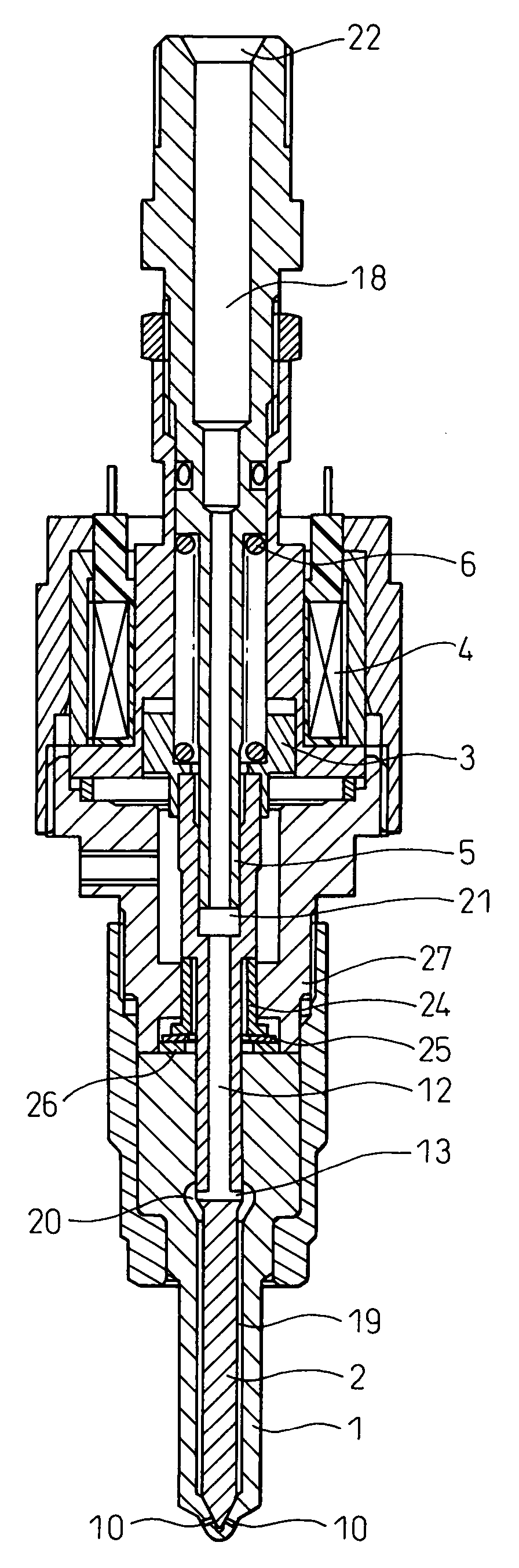
[0037] The best mode for embodying the invention will be explained below with reference to the drawings. FIG. 1 shows a fuel injection valve according to the invention. In FIG. 1, reference numeral 1 designates a nozzle, numeral 2 a needle, numeral 3 an armature, numeral 4 a solenoid, numeral 5 a balance rod, and numeral 6 a coil spring.

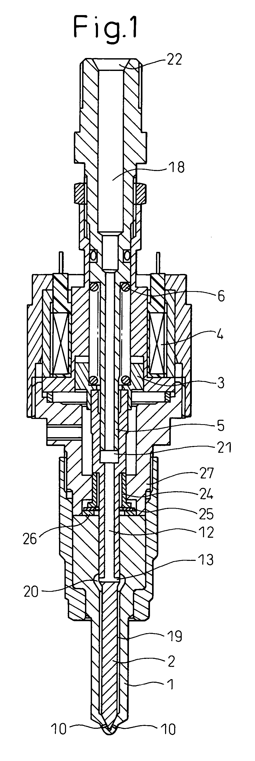
[0038]FIG. 2 shows the nozzle 1. As shown in FIG. 2, a space 7 is formed along the longitudinal axis of the fuel injection valve (hereinafter referred to simply as “the longitudinal axis”) of the nozzle 1. This space 7 is narrowed (the lower side in the drawing is hereinafter referred to as “the forward end side”, and the upper side as “the base end side”) and the inner wall surface 9 for defining the space 7 assumes a conical shape at the forward end side of the nozzle 1. Also, fuel injection ports 10 are formed at the forward end of the nozzle 1. The fuel injection ports 10 communicate with the space 7.

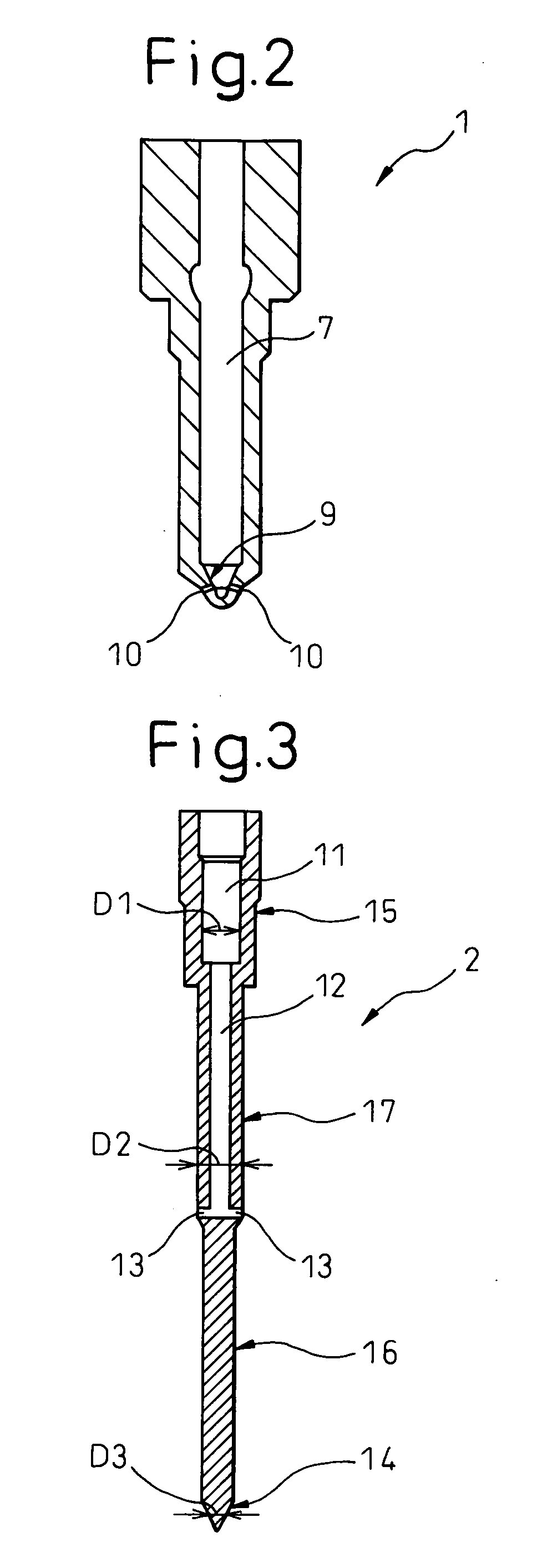
[0039]FIG. 3 shows the needle 2. Though not d...

second embodiment

[0065] Next, the operation of the fuel injection valve will be briefly explained. Also in this embodiment, once power is supplied to the solenoid 4, the armature 3 is attracted toward the base end side by the electromagnetic force generated by the solenoid 4. As a result, the needle 2 is also attracted toward the base end side, and the needle seat wall surface 14 comes off from the nozzle seat wall surface 9. In this way, the fuel that has reached the neighborhood of the forward end portion of the needle 2 reaches the forward end portion of the needle 2 by circumventing the needle 2, and is injected from the fuel injection port 10. Once power supply to the solenoid 4 is stopped, on the other hand, the electromagnetic force also ceases to be generated from the solenoid 4. Then, the needle 2 is moved toward the fuel injection port 10 at the forward end side mainly by the urging force of the coil spring 6, and, finally, the needle seat wall surface 14 comes into contact with the nozzl...


PUM


Abstract

A fuel injection valve includes a fuel injection port, a needle for cutting the fuel flow into the fuel injection port and a needle mover for moving the needle away from the fuel injection port and allowing the fuel to flow into the fuel injection port. When the needle is moved away from the fuel injection port by the needle mover, the force is applied by a force applicator to the needle away from the fuel injection port only during the period when the needle is moved away from the fuel injection port to less than a predetermined degree.

Description

BACKGROUND OF THE INVENTION [0001] 1. Field of the Invention [0002] The present invention relates to a fuel injection valve. [0003] 2. Description of the Related Art [0004] Japanese Unexamined Patent Publication No. 2000-257534 discloses a fuel injection valve for injecting fuel into the combustion chamber of the internal combustion engine. This fuel injection valve comprises a fuel injection port (referred to, in the publication cited above, as “the fuel injection holes” designated by reference numeral 8) and a member for closing the fuel injection port (in the cited publication, corresponds to a movable portion 4A including a plunger 4, a rod 5 and a valve body 6, and hereinafter referred to as “the movable portion” as in the cited publication). In this fuel injection valve, the movable portion is subjected to the force generated by the fuel pressure (hereinafter referred to as “the valve opening force due to the fuel pressure”) acting on the movable portion in the direction to op...

Claims


Application Information

Patent Timeline
Patent Type & Authority Applications(United States)
IPC IPC(8): F02M51/00B05B1/30F02M47/00F02M51/06F02M61/04F02M61/10F02M61/18F02M61/20
CPCF02M51/0671F02M61/205F02M61/042
Inventor GOTO, MORIYASUENOMOTO, SHIGEIKUOMAE, KAZUHIRO
Owner TOYOTA JIDOSHA KK
Why Eureka
Try Eureka