
cng/lpg gas nozzle

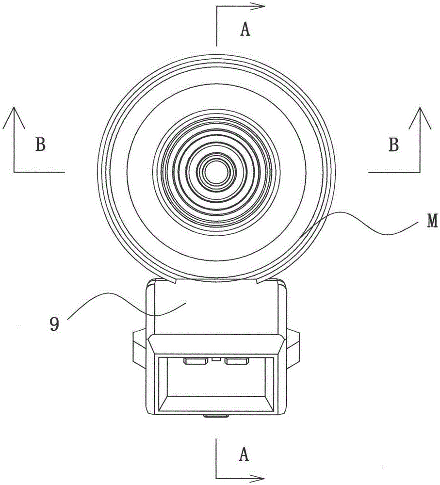
An air outlet nozzle and nozzle housing technology, which is applied in the field of gas vehicle equipment, can solve the problems of high impact noise of the guide cylinder and the static iron core, the inability to process the wear resistance of the guide cylinder, and the inability to solve the problem of scrapping of highly worn nozzles. Avoid damage, facilitate disassembly and maintenance, and reduce noise

Active Publication Date: 2016-06-08
上海依相动力系统有限公司
View PDF7 Cites 3 Cited by
  • Summary
  • Abstract
  • Description
  • Claims
  • Application Information

AI Technical Summary

Problems solved by technology

[0004] At present, high-pressure (6bar) gas nozzles (upper and lower gas inlet and outlet types) have the problems of low opening ability, slow opening speed and low durability and reliability. The cylinder cooperates with the long columnar piston-type armature in the middle to control the air outlet. Due to the large volume and mass of the armature, the opening speed is slow, and the impact force on the guide cylinder and the static iron core during the movement causes a lot of noise.
The friction between the inner wall of the guide cylinder and the armature is relatively large. Since the guide cylinder and the nozzle housing adopt an integrated structure, it is impossible to process the inner wall of the guide cylinder to increase its wear resistance, so it cannot solve the problem of nozzle scrapping due to high wear; The air outlet nozzle and the nozzle housing adopt an integrated spray hole, if the product is damaged, it will not be repaired; the sealant for the nozzle to control the air outlet is bonded to the armature, which will undoubtedly increase the weight of the armature and affect its opening speed. At the same time, the damage to the surface coating of the armature cannot be avoided when the sealing rubber is used as vulcanized adhesive

Method used


Image

  • cng/lpg gas nozzle
  • cng/lpg gas nozzle
  • cng/lpg gas nozzle

Examples


Embodiment Construction

[0033] In order to make the technical means, creative features, goals and effects achieved by the present invention easy to understand, the present invention will be further described below in conjunction with specific illustrations.

[0034] It is easy to understand that, according to the technical solution of the present invention, those skilled in the art can propose various structural modes and implementation modes that can be replaced without changing the essence and spirit of the invention. Therefore, the following specific embodiments and drawings are only exemplary descriptions of the technical solution of the present invention, and should not be regarded as the entirety of the present invention or as a limitation or restriction on the technical solution of the present invention.

[0035] It should be noted that the orientations of the words "upper" and "lower" used in the following description refer to the upper and lower directions in the drawings, and the words "inne...


PUM


Abstract

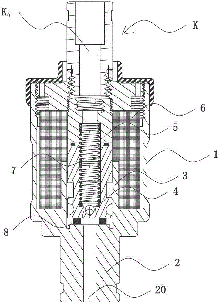
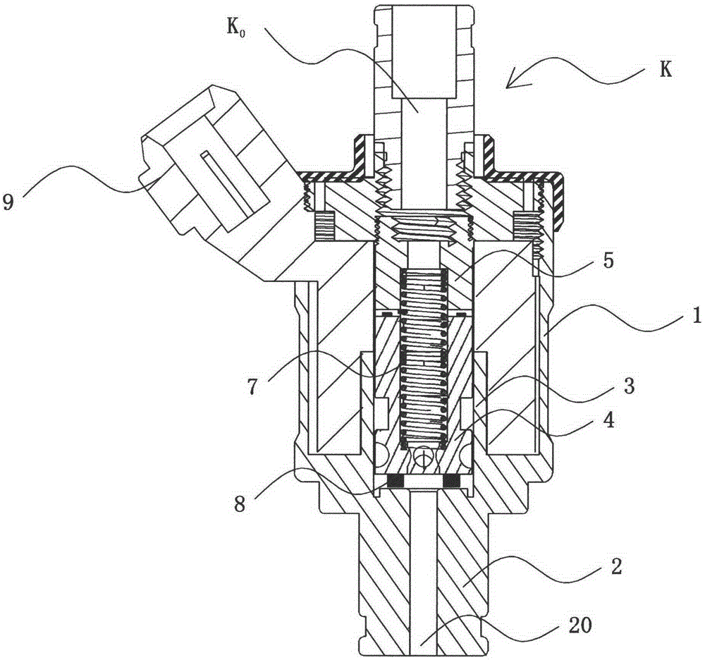
The invention discloses a CNG / LPG (compressed natural gas / liquefied petroleum gas) fuel gas spray nozzle, which comprises a spray nozzle casing, a gas inlet joint, a casing sealing structure and an internal fuel passage part, wherein the spray nozzle casing comprises a fuel gas outlet nozzle part with a spraying hole, the gas inlet joint, the casing sealing structure and the internal fuel passage part are arranged on the spray nozzle casing, the tail end of the spraying hole is provided with a guide tube, a coil assembly is arranged outside the guide tube, an armature, a static iron core, a spring and sealing rubber are arranged in the guide tube, the fuel gas outlet nozzle part is provided with a nozzle core installing hole with internal screw threads and a gas outlet nozzle arranged at a nozzle core installing hole part, the tail end of the nozzle core installing hole is a guide tube assembly cavity which is arranged on the spray nozzle casing and is provided with internal screw threads, the guide tube assembly cavity is provided with a guide tube in threaded connection, and the armature in a flat round sheet type structure is arranged in the guide tube. The armature in the flat round sheet type structure has the advantages of light weight, high starting speed and high efficiency, the impact force on the guide tube and the static iron core is small, and the noise is low. The dismountable gas outlet nozzle brings convenience for the regulation and the dismounting maintenance on the fuel gas spray nozzle, the sealing rubber is fixed on the gas outlet nozzle, the load of the armature is reduced, and the damage to the surface coating of the armature caused by vulcanization adhesives is also avoided.

Description

technical field [0001] The invention relates to gas vehicle equipment, in particular to a CNG / LPG gas nozzle. Background technique [0002] Known columnar piston type armature nozzle, its structure sees Figure 1~5 , including a nozzle housing 1, which is roughly cylindrical, and the front end of the nozzle housing 1 is provided with an air outlet nozzle 2 with an integrated structure with the nozzle housing, and the air outlet nozzle is provided with an injection hole 20 for injecting fuel to the engine. The end of the hole is the guide cylinder 3 inside the nozzle housing. The guide cylinder and the nozzle housing have an integrated structure. The guide cylinder is equipped with an armature 4 to control the air outlet. For the structure of the armature, see Figure 4 , Figure 5 , the armature structure is composed of upper and lower bodies to form a cylindrical piston structure, a static iron core 5 with an axial through hole is arranged above the armature, and a coil as...

Claims


Application Information

Patent Timeline
Patent Type & Authority Patents(China)
IPC IPC(8): F02M21/02
CPCY02T10/30
Inventor 杨国清
Owner 上海依相动力系统有限公司
Learn More