Turbulent flow reducer

Inactive Publication Date: 2005-04-07
PREMIER FARNELL +1
View PDF14 Cites 22 Cited by
  • Summary
  • Abstract
  • Description
  • Claims
  • Application Information

AI Technical Summary

Benefits of technology

[0015] It is a further object of the invention to provide a stream shaper that is small and does not significantly increase the weight of a nozzle or make it more difficult to manipulat

Problems solved by technology

Turbulence in the water delivered to a discharge nozzle reduces the reach of the water jet discharged from the nozzle and causes water to separate from the jet instead of being delivered to the desired location.
This allowed a reduction in turbulence before water entered

Method used


Image

  • Turbulent flow reducer
  • Turbulent flow reducer
  • Turbulent flow reducer

Examples


Example

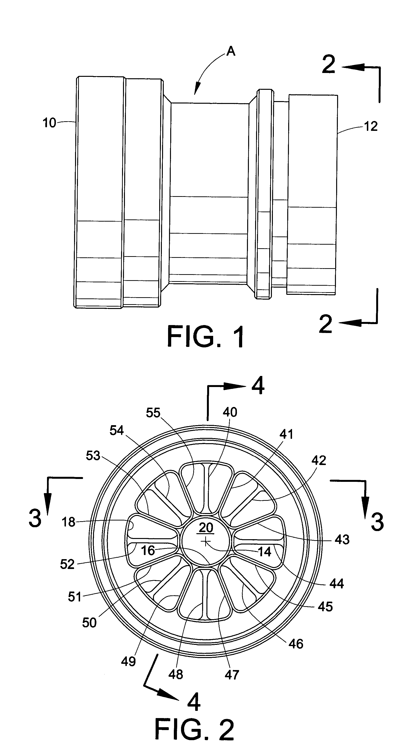
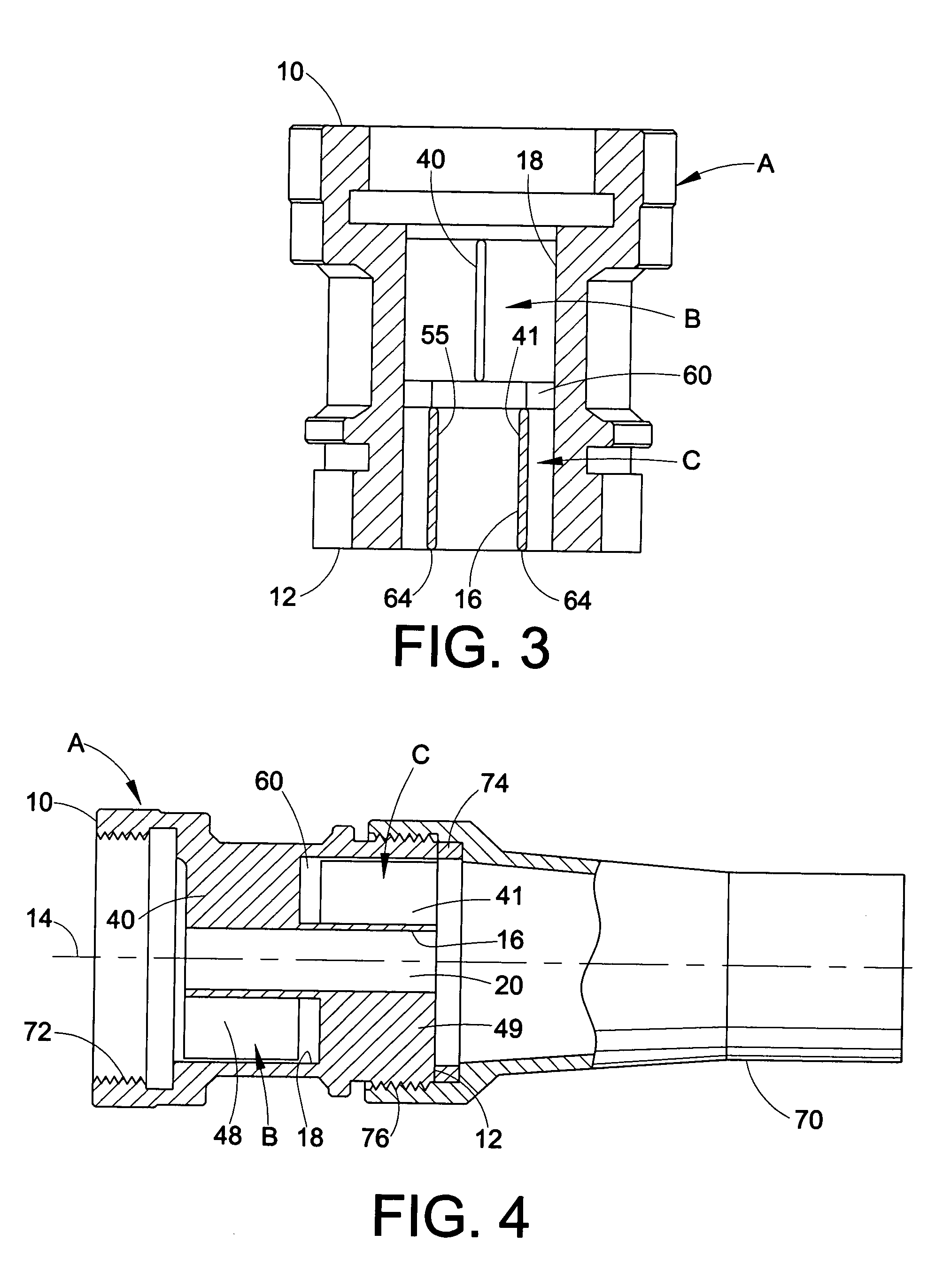
[0026] Referring now to the drawings, wherein the showings are for purposes of illustrating certain preferred embodiments of the invention only and not for purposes of limiting same, FIG. 1 shows a stream shaper in the form of a generally cylindrical discharge pipe to which a discharge nozzle is connectable. In the arrangement shown, liquid flows from an inlet end 10 toward a discharge end 12, although it will be appreciated that the flow direction can be reversed while achieving the same performance.

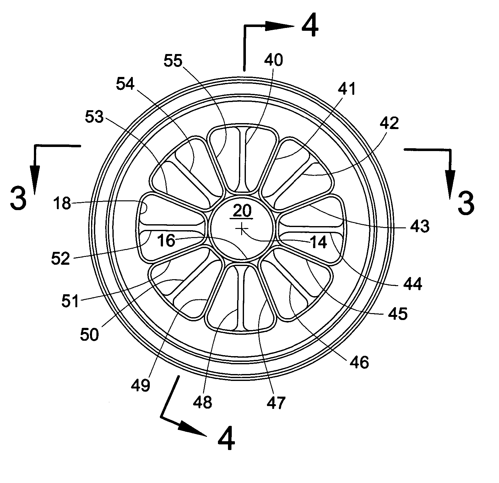
[0027] The interior of stream shaper A has a plurality of longitudinal passages extending therethrough parallel to central longitudinal axis 14. The interior of stream shaper A includes inner and outer cylindrical walls 16, 18 and a central cylindrical passage 20 extends through inner cylindrical wall 16.

[0028] Vanes 40-55 extend between inner and outer cylindrical walls 16, 18 radially of and parallel to longitudinal axis 14. The alternate or odd numbered vanes are axially displaced ...


PUM


Abstract

A stream shaper for reducing turbulent flow has a plurality of circumferentially-spaced vanes, with alternate vanes being axially-spaced from the remaining vanes. This axial separation of vane groups reduces the flow restriction caused by the vanes at any given cross section along the length of the stream shaper as compared to a stream shaper having the same total number of vanes extending the full length of the stream shaper. Axially spacing alternate vanes from the remaining vanes also permits a significant reduction in the overall length of the stream shaper while providing the turbulence reducing effects of a much longer stream shaper with vanes that extend uninterrupted the full length of the stream shaper.

Description

BACKGROUND OF THE INVENTION [0001] This application relates to the art of fluid flow control and, more particularly, to reducing turbulence in a flowing stream. The invention is particularly applicable for use with firefighting nozzles and will be described with specific reference thereto. However, it will be appreciated that the invention has broader aspects and can be used in any environment for reducing turbulence in a fluid stream. [0002] Turbulence in the water delivered to a discharge nozzle reduces the reach of the water jet discharged from the nozzle and causes water to separate from the jet instead of being delivered to the desired location. Separation of liquid from the discharged water jet is visible as a mist that produces a long footprint where the water falls to the ground. [0003] Early efforts to reduce turbulence included the use of a long smooth discharge pipe upstream from the discharge nozzle. This allowed a reduction in turbulence before water entered the dischar...

Claims


Application Information

Patent Timeline
IPC IPC(8): A62C33/00B05B1/14B05B1/34
CPCB05B1/34B05B1/3402
Inventor PETIT, KEVIN J.
Owner PREMIER FARNELL
Why Eureka
Try Eureka