Closet partition system

a closet and partition technology, applied in the field of closet partition systems, can solve the problems of inability to meet the needs of closet storage space utilization, and inability to provide resilient deformation materials with adequate strength for closet partition systems bearing heavy loads, etc., to achieve the effect of reducing the number of steps required for installation, eliminating difficult manipulation, and high load bearing capacity

Active Publication Date: 2007-08-28
BILCO PRODS ACQUISITION
View PDF14 Cites 6 Cited by
  • Summary
  • Abstract
  • Description
  • Claims
  • Application Information

AI Technical Summary

Benefits of technology

[0009]The closet partition systems of this invention include a simplified mounting rail and bracket arrangement that overcomes problems associated with, and improves upon, known arrangements for mounting vertical members, such as partitions, to a wall. In particular, the mounting rail and the bracket for the closet partition system of the invention reduces the number of steps required for installation as compared with other systems that provide high load bearing capability, and eliminates difficult manipulations, whereby an individual may easily install a closet partition system without requiring assistance from a second person. Further, the mounting rail and bracket are configured to provide stable support that prevents the possibility of accidental dislodgment of the bracket from the mounting rail.
[0010]In one aspect of the invention, the closet partition system includes a mounting rail and a bracket for connecting a vertical member, such as a partition, to the mounting rail. The mounting rail includes a vertical back for attachment to a wall, a horizontal ledge projecting from the back, and a hook including a first section extending horizontally from the back and a second section extending downwardly from an outwardly projecting end of the first section and toward the ledge. The bracket includes an elongate notch extending vertically downwardly from an upper edge of the bracket for receiving the second section of the hook. This arrangement facilitates design of a closet partition system that is very easy to use, which is capable of providing very high load bearing capability, and which facilitates repeated disassembly and reassembly without degradation of the components or the load bearing properties of the components.

Problems solved by technology

It is now well recognized that the typical closet having one or more hanging rods and one or more shelves supported above the rod or rods does not usually facilitate the most efficient use of the available storage space in the closet.
A deficiency with the support system disclosed in the Phelps patent relates to the snap-together features of the system.
As a practical matter, inexpensive, resiliently deformable materials may not provide adequate strength for closet partition systems bearing heavy loads.
However, the brackets and supported cabinetry or the like may be easily moved upwardly by an inadvertently applied upward force to the cabinetry or other supported units, and could under certain circumstances become inadvertently dislodged.
However, this arrangement has the disadvantage of adding steps to the assembly process, as well as the disassembly process, and could prevent multiple reconfigurations due to damage to the mounting rail caused by repeatedly attaching the bracket to the mounting rail using fasteners.
This system requires use of a standoff attached to the lower backside of a modular unit supported by the bracket, and therefore is not particularly well suited for supporting vertical panels or partitions, and still exhibits a substantial potential for undesired dislodgement if an inadvertent upward force of sufficient magnitude is applied to a supported partition.

Method used


Image

  • Closet partition system
  • Closet partition system
  • Closet partition system

Examples


Embodiment Construction

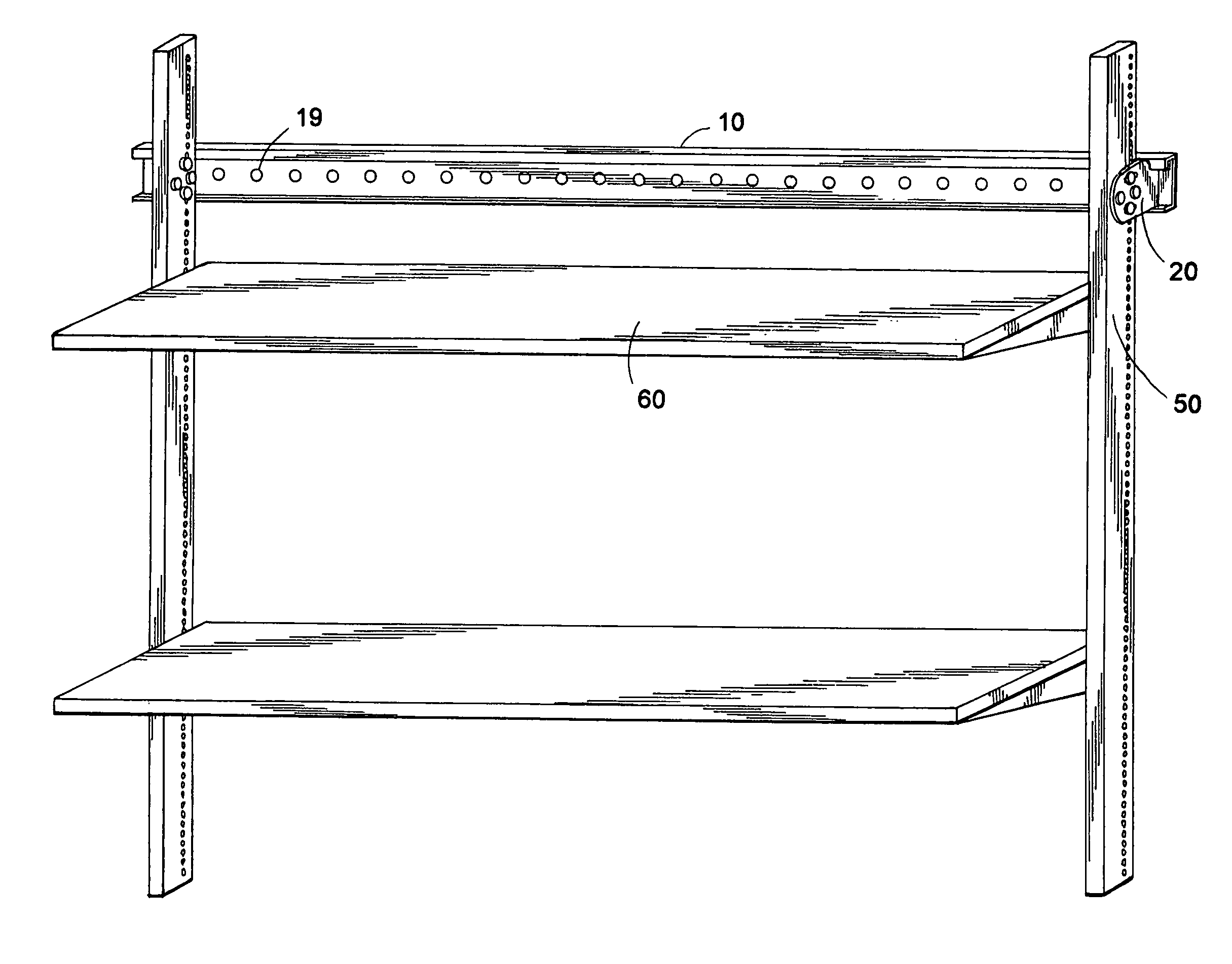
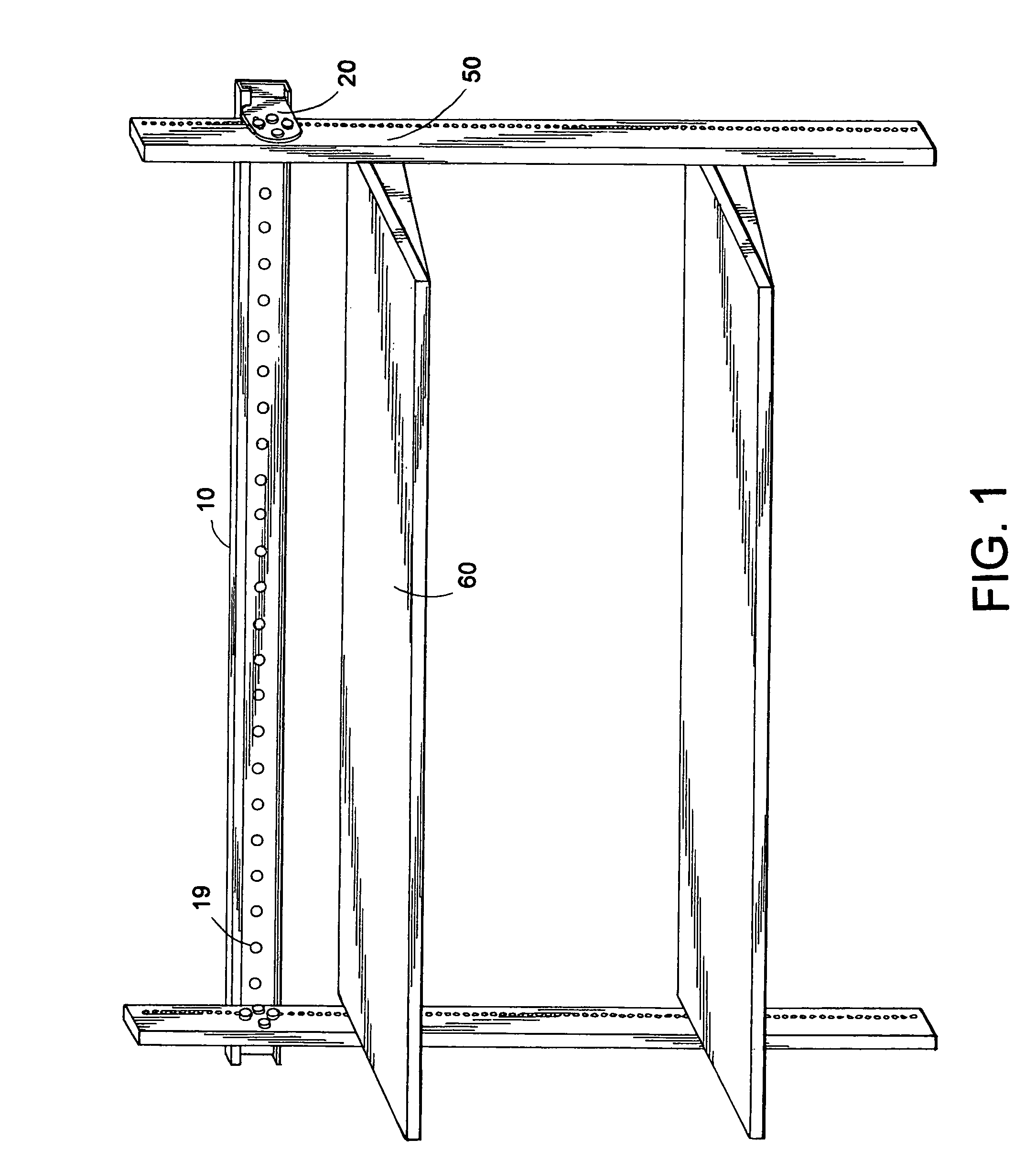
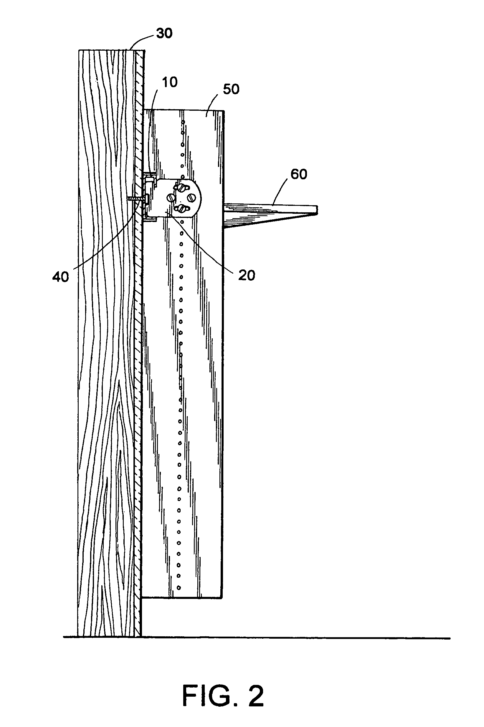
[0015]As shown in FIGS. 1–3, the closet partition system in accordance with this invention includes an interlocking wall mounting rail 10 and a bracket 20. Wall mounting rail 10 has a generally inverted J-shaped cross section, which includes a back section 12 for attachment of rail 10 to a wall 30, a lower horizontal ledge 14 projecting from a lower edge of back section 12 away from wall 30, and a hook having a first section 16 extending horizontally from an upper edge of back section 12 away from wall 30 and a second section 18 extending downwardly from the outwardly projecting end of first section 16 and toward ledge 14.

[0016]Mounting rail 10 may be fastened to wall 30 in generally any suitable manner that will provide adequate support for the components of the closet partition system which are suspended on rail 10. Mounting rail 10 can be provided with a plurality of apertures 19, which are uniformly spaced apart to facilitate attachment of rail 10 to wall 30 with threaded screws...


PUM


Abstract

A closet partition system includes a simplified arrangement that reduces the number of steps required for installation and eliminates difficult manipulations, whereby an individual may easily install a closet partition system without requiring assistance. The mounting rail and bracket provide stable support that prevents the possibility of accidental dislodgement of the bracket from the mounting rail. The mounting rail includes a vertical back for attachment to a wall, a horizontal ledge projecting from the back, and a hook having a first section extending horizontally from the back and a second section extending downwardly toward the ledge. The bracket includes an elongate notch extending downwardly from an upper edge of the bracket for receiving the second section of the hook. This arrangement provides a closet partition system that is easy to use, capable of providing very high load bearing capability, and facilitates repeated disassembly and reassembly without degradation of the components.

Description

FIELD OF THE INVENTION[0001]This invention relates to closet partition systems, and more particularly to closet partition systems incorporating improved wall-mountable bracket support hardware.BACKGROUND OF THE INVENTION[0002]It is now well recognized that the typical closet having one or more hanging rods and one or more shelves supported above the rod or rods does not usually facilitate the most efficient use of the available storage space in the closet. In order to more effectively utilize closet space, various modular-type storage unit systems and closet partition systems have been developed. The preferred modular systems typically are comprised of a few basic components, such as mounting rails, vertical panels, horizontal shelves, hanging rods, and various mounting brackets, which allow the components to be assembled in a variety of different manners to facilitate rearrangement as the users needs change. It is desirable that the mounting brackets and other hardware used for ass...

Claims


Application Information

Patent Timeline
Patent Type & Authority Patents(United States)
IPC IPC(8): A47F5/08
CPCA47B96/067
Inventor STRATING, MICHAEL J.SLIGH, THOMAS H.GILCREST, JOEL P.
Owner BILCO PRODS ACQUISITION
Why Eureka
Try Eureka