
Method and arrangement for handling information packets via user selectable relay nodes

a relay node and information packet technology, applied in the field of communication, can solve the problems of inability of users to influence the routing of their packets, inability of intermediary nodes to redirect packets, and difficulty in ensuring the safety of users, so as to improve throughput, minimize costs, and enhance security

Inactive Publication Date: 2007-08-14
TELEFON AB LM ERICSSON (PUBL)
View PDF8 Cites 5 Cited by
  • Summary
  • Abstract
  • Description
  • Claims
  • Application Information

AI Technical Summary

Benefits of technology

[0032]An advantage of the invention is that the method is useful for protection against interceptors by hiding the identities of the communicating parties. Moreover, an interceptor cannot find out which packets are related in the forward and return streams of packets.
[0033]An advantage of the invention is that traffic between an overlay network of nodes can be dynamically arranged without interfering with the interior behavior of the intermediary networks that are used. This can e.g. be used to induce packets having different types of service to take different routes by travelling via different relay nodes, and to direct traffic to different routes at different times in order to improve the throughput and in order to minimize costs.
[0034]An advantage of the invention is that the overlay network of nodes can consist of a relatively small number of nodes and their configuration can be relatively static while the number of originating nodes and destination nodes can be large and their configuration very dynamic.
[0035]Another advantage of the invention is that an interceptor at any relay node cannot relate a packet to a specific originator or destination. Due to the herein disclosed address substitution it is much more difficult to manipulate the communication between communicating parties as packets are anonymously mixed into the total flow of traffic.
[0036]A further advantage of the invention is that forward and return packets cannot be correlated, and thus the security is enhanced.
[0037]A yet further advantage of the invention is that it is possible to influence how packets are routed via intermediary networks based on quality of service requirements, service level agreements with different network providers and costs.

Problems solved by technology

The main problem with routing in a conventional internet is that the users cannot influence the routing of their packets.
Another problem with routing in a conventional internet is that, as the source and destination addresses are placed in the header of each packet, an intruder may easily trace messages.
A further problem with routing in a conventional internet is that it is difficult for an intermediary node to redirect a packet via alternate sequences of nodes based on user preferences.
A yet further problem with the method according to U.S. Pat. No. 5,353,283 is that it can only function with a new standard, and that said new standard must be implemented in every network over which the packets passes.

Method used


Image

  • Method and arrangement for handling information packets via user selectable relay nodes
  • Method and arrangement for handling information packets via user selectable relay nodes
  • Method and arrangement for handling information packets via user selectable relay nodes

Examples


Embodiment Construction

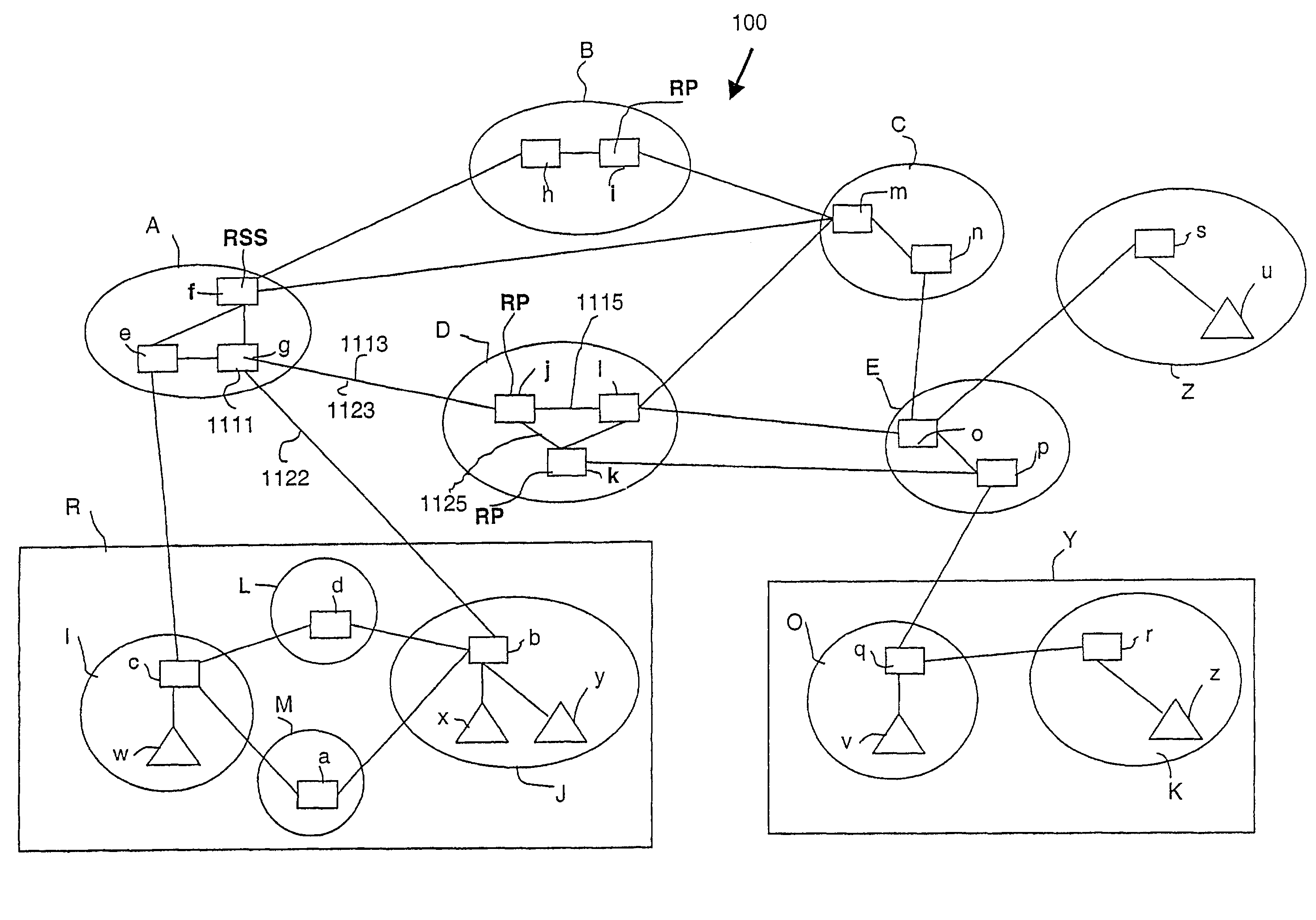
[0055]An Internet communication network 100 is depicted in FIG. 1 including five transit or backbone networks A, B, C, D, and E and three stub networks R, Y, and Z. A “backbone” network is an intermediary network which conveys communicated data from one network to another network. A “stub” network is a terminal or endpoint network from which communicated data may only initially originate or ultimately be received. Each network, such as the stub network R, includes one or more interconnected sub-networks I, J, L and M. As used herein, the term “sub-network” refers to a collection of one or more nodes, e.g., (d), (a), (b, x, y), (q, v), (r, z), (s, u), (e, f, g), (h, i), (j, k, l), (m, n), and (o, p), interconnected by wires or switches for local inter-nodal communication. Nodes within a parenthesis belong to the same sub-network. Each sub-network may be a local area network or LAN. Each sub-network has one or more interconnected nodes of which nodes u, v, w, x, y, z are host computer...


PUM


Abstract

The invention is related to a method in a communication network for handling traffic, such as data packets, from source nodes to destination nodes, via user selectable relay nodes. The relay nodes form an overlay network of nodes operated and managed by an overlay network operator. Communication between relay nodes relies on using packet forwarding services of intermediate networks being operated and managed independently by other operators. For any source / destination pair the overlay network operator may select an appropriate sequence of relay nodes to be passed depending on the required quality of service and the performance of different intermediate networks. The invention enables the control of the spreading of traffic between any two end-points over several alternative relay routes.

Description

[0001]This application is a national stage entry of PCT / EP01 / 05647, filed May 17, 2001, and claims priority of European Application No. 00112673.9, which was filed Jun. 15, 2000.FIELD OF INVENTION[0002]The present invention relates to communication in a communication network. In particular, the present invention relates to a method, a corresponding computer program and an arrangement for enabling users to influence the routing of their information packets.DESCRIOTION OF RELATED ART[0003]An internet is any set of networks interconnected with routers. The Internet is the biggest example of an internet. An internet may by functioning over wireline links, or over air interfaces, e.g. by means of short range radio waves, such as Bluetooth, or a mobile network.[0004]The Internet is the worldwide interconnected WAN, based on the TCP / IP protocol suite. The complex problem of routing on large networks can be simplified by structuring a network into a hierarchy of smaller networks, where each...

Claims


Application Information

Patent Timeline
Patent Type & Authority Patents(United States)
IPC IPC(8): G06F15/173H04L12/28H04L45/42
CPCH04L45/00H04L45/04H04L45/308H04L45/34H04L45/42H04L45/64
Inventor JONSSON, BJORN
Owner TELEFON AB LM ERICSSON (PUBL)
Learn More