Systems and methods using an electrified projectile

a technology of electrification and projectiles, applied in the field of systems and methods using electrified projectiles, can solve the problems of limited application of conventional conducted energy weapons using gunpowder propellants, limited effect of stimulus signals of the type described by cover, and pain in the target, so as to achieve more accurate and/or repeatable electrode spacing, reduce cost, and improve the effect of immobilizing stimulus signal delivery

Active Publication Date: 2005-04-07
AXON ENTERPRISE INC
View PDF0 Cites 27 Cited by
  • Summary
  • Abstract
  • Description
  • Claims
  • Application Information

AI Technical Summary

Benefits of technology

[0015] According to various aspects of the present invention, an apparatus for immobilizing a target includes electrodes deployed after contact is made between the apparatus and the target. Spacing of deployed electrodes may be more accurate and / or more repeatable for more effective delivery of an immobilizing stimulus signal.
[0016] In another implementation, a system for immobilizing a target includes a launch device and a projectile. The projectile is not tethered to the launch device. The projectile deploys an electrode after the projectile contacts the target. By deploying an electrode after contact, a distance between electrodes is less dependent on range from the launch device to the target. Consequently, targets at various ranges receive more uniform stimulation. A larger number of applications for energy weapons may be met with projectiles, methods, and systems of the present invention due to various aspects including lower cost, lower complexity, higher reliability, greater range and accuracy, and improved effectiveness in various combinations according to the implementation.

Problems solved by technology

A stimulus signal comprising a series of relatively high voltage pulses are delivered through the wires and into the target, causing pain in the target.
Effectiveness of a stimulus signal of the type described by Cover is limited.
Conventional conducted energy weapons that use a gunpowder propellant have limited application.
These weapons are classified as firearms and are subject to heavy restrictions in the United States, severely limiting their marketability.
These weapons have limited application because close proximity typically decreases the safety of the person armed with the weapon.
The EMD waveform apparently overrides the target's nervous system's muscular control, causing involuntary lockup of the skeletal muscle, and may result in complete immobilization of the target.
Unfortunately, the relatively higher energy EMD waveform is generally produced from a higher power capability energy source.
Conventional conducted energy weapons have limited range to achieve an effective separation of two electrodes to stimulate the target by an electric current passing between the electrodes.
Higher cost and lower reliability result.
A range sensing system could malfunction by having a narrow field of view, for example, where the device could impact the target at such an oblique angle that the range sensor never effectively senses the target until it is too close to effectively deploy the second electrode.
Alternatively, if the device is fired in a direction where the projectile must pass close by an obstacle en route to the target, the range sensor might detect an object next to its trajectory and prematurely fire the second electrode, causing the second electrode to miss the target.
Such arrays, when in flight, are inherently aerodynamically unstable.
Applications for energy weapons will remain limited, hampering law enforcement and failing to provide increased self defense to individuals.

Method used


Image

  • Systems and methods using an electrified projectile
  • Systems and methods using an electrified projectile
  • Systems and methods using an electrified projectile

Examples


Embodiment Construction

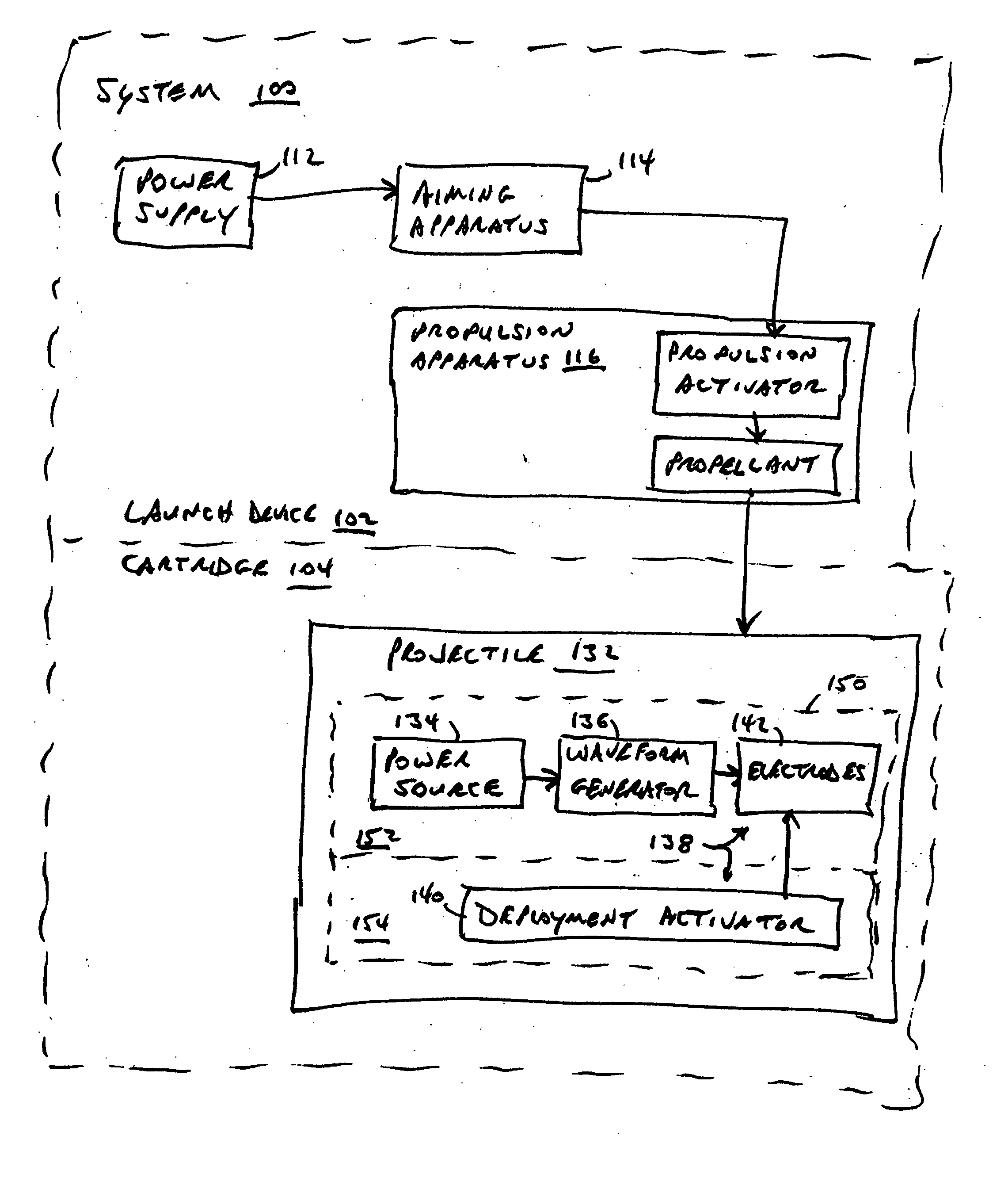
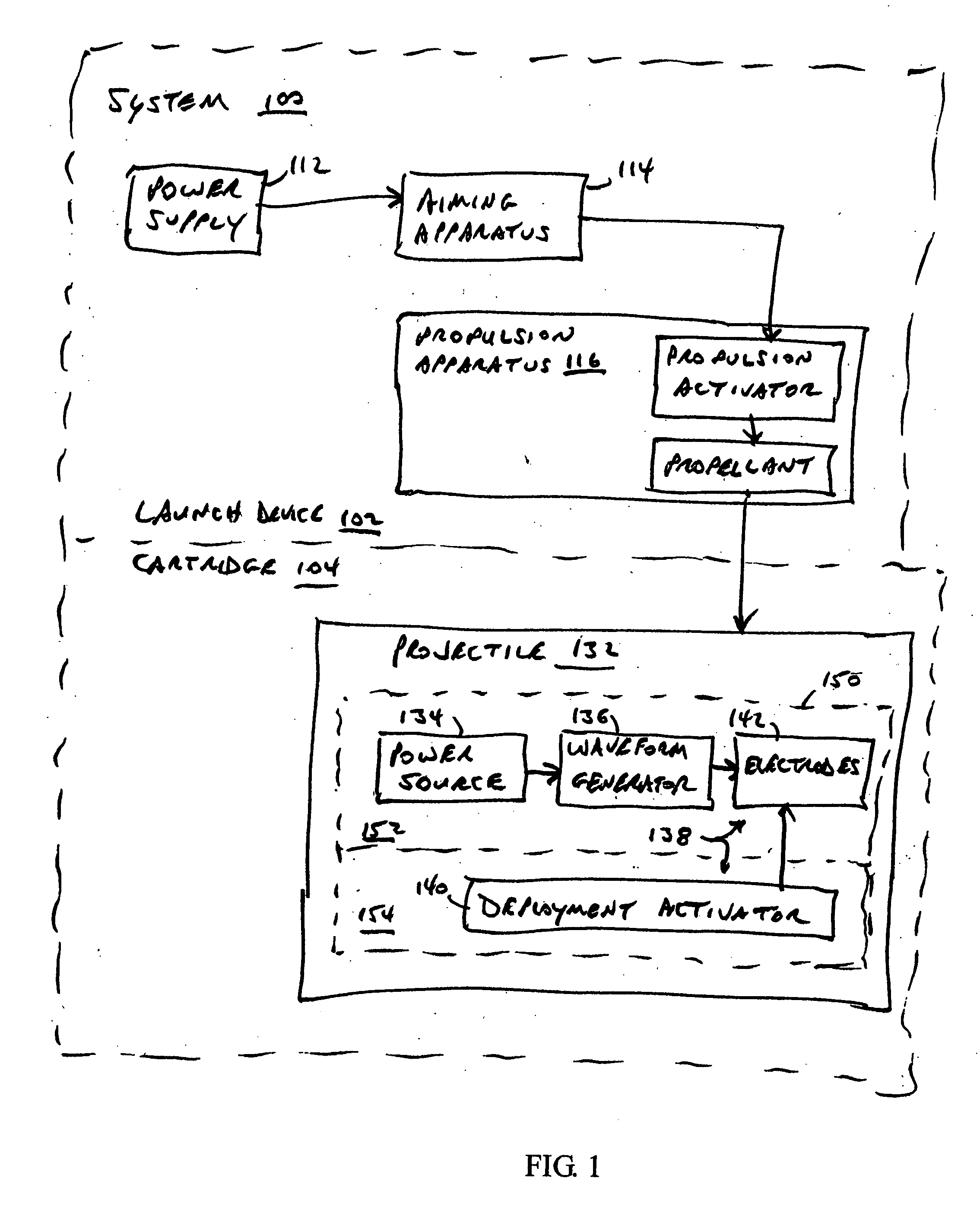
[0039] A system according to various aspects of the present invention delivers a stimulus signal to an animal to immobilize the animal. Immobilization is suitably temporary, for example, to remove the animal from danger or to thwart actions by the animal such as for applying more permanent restraints on mobility. Electrodes may come into contact with the animal by the animal's own action (e.g., motion of the animal toward an electrode), by propelling the electrode toward the animal (e.g., electrodes being part of an electrified projectile), by deployment mechanisms, and / or by gravity. For example, system 100 of FIGS. 1-9 includes launch device 102 and cartridge 104. Launch device 104 includes power supply 112, aiming apparatus 114, and propulsion apparatus 116. Propulsion apparatus 116 includes propulsion activator 118 and propellant 120. In an alternate implementation, propellant 120 is part of cartridge 104.

[0040] Any conventional materials and technology may be employed in the m...


PUM


Abstract

An apparatus for immobilizing a target includes electrodes deployed after contact is made between the apparatus and the target. Spacing of deployed electrodes may be more accurate and/or more repeatable for more effective delivery of an immobilizing stimulus signal.

Description

CROSS-REFERENCE TO RELATED APPLICATIONS [0001] This application claims priority under 35 U.S.C. § 119(e) to copending U.S. patent application 60 / 509,577 filed Oct. 7, 2003 by Patrick W. Smith et al., incorporated herein by reference.GOVERNMENT LICENSE RIGHTS [0002] The present invention may have been, in part, derived in connection with U.S. Government sponsored research. Accordingly, the U.S. Government has a paid-up license in this invention and the right in limited circumstances to require the patent owner to license others on reasonable terms as provided for by the terms of contract No. N00014-02-C-0059 awarded by the Office of Naval Research.BACKGROUND OF THE INVENTION [0003] Embodiments of the present invention generally relate to systems and methods using an electrified projectile for reducing mobility in a person or animal. [0004] Weapons that deliver electrified projectiles have been used for self defense and law enforcement where the target struck by the projectile is a hu...

Claims


Application Information

Patent Timeline
Patent Type & Authority Applications(United States)
IPC IPC(8): F41H13/00F42B12/36H05C1/06
CPCF41H13/0031H05C1/06F42B12/36F42B5/24F42B8/00H01T23/00F42B12/00
Inventor SMITH, PATRICK W.NERHEIM, MAGNE H.
Owner AXON ENTERPRISE INC
Why Eureka
Try Eureka