Branch wire tie band, binding structure, and method of binding a wiring harness

a branch wire and tie-band technology, applied in the direction of hose connections, flexible elements, packaging, etc., can solve the problems of reducing the positioning precision of the branched portion, excessive time required to perform the tape wrapping operation, and the quality of the tape wrap may vary, so as to achieve convenient tightening and simple and economical

Inactive Publication Date: 2005-04-14
SUMITOMO WIRING SYST LTD
View PDF6 Cites 145 Cited by
  • Summary
  • Abstract
  • Description
  • Claims
  • Application Information

AI Technical Summary

Benefits of technology

[0011] Taking the above-noted shortcomings into consideration, the present invention provides, inter alia, a branch wire tie band that is able to wrap around a wire bundle in a cross pattern at a wire branch point, closely follow the contour of the wire bundle, and be easily tightened. The present invention also provides a method of using the branch wire tie band, and a tie band binding structure. Further, the present invention provides a simple and economical wire branch tie band structure that combines tie bands with a flat anchor plate to wrap a bundle of wires at a branch location.

Problems solved by technology

There are problems associated with this operation.
For example, training and skill are required to perform the tape wrapping operation at the branch locations, the quality of the tape wrap may vary due to differences in the skill of the people wrapping the wires, and excessive time is required to perform the tape wrapping operation due to the many locations where wires branch off of the main harness.
This can lead to a change in the taping location where the wires branch off, and thus reduce the positioning precision of the branched portion.
This makes it difficult for straps 8a to follow the contour of the wire bundle as they wrap around it, allows the formation of a gap between the bands and wires, and reduces binding pressure which can result in the problem of the branch wires branching off from the trunk wires at an imprecise location.
It thus becomes expensive to fabricate the dies needed to manufacture tie band 6 in different configurations.

Method used


Image

  • Branch wire tie band, binding structure, and method of binding a wiring harness
  • Branch wire tie band, binding structure, and method of binding a wiring harness
  • Branch wire tie band, binding structure, and method of binding a wiring harness

Examples


first embodiment

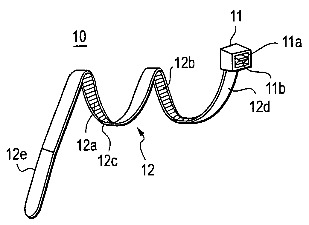
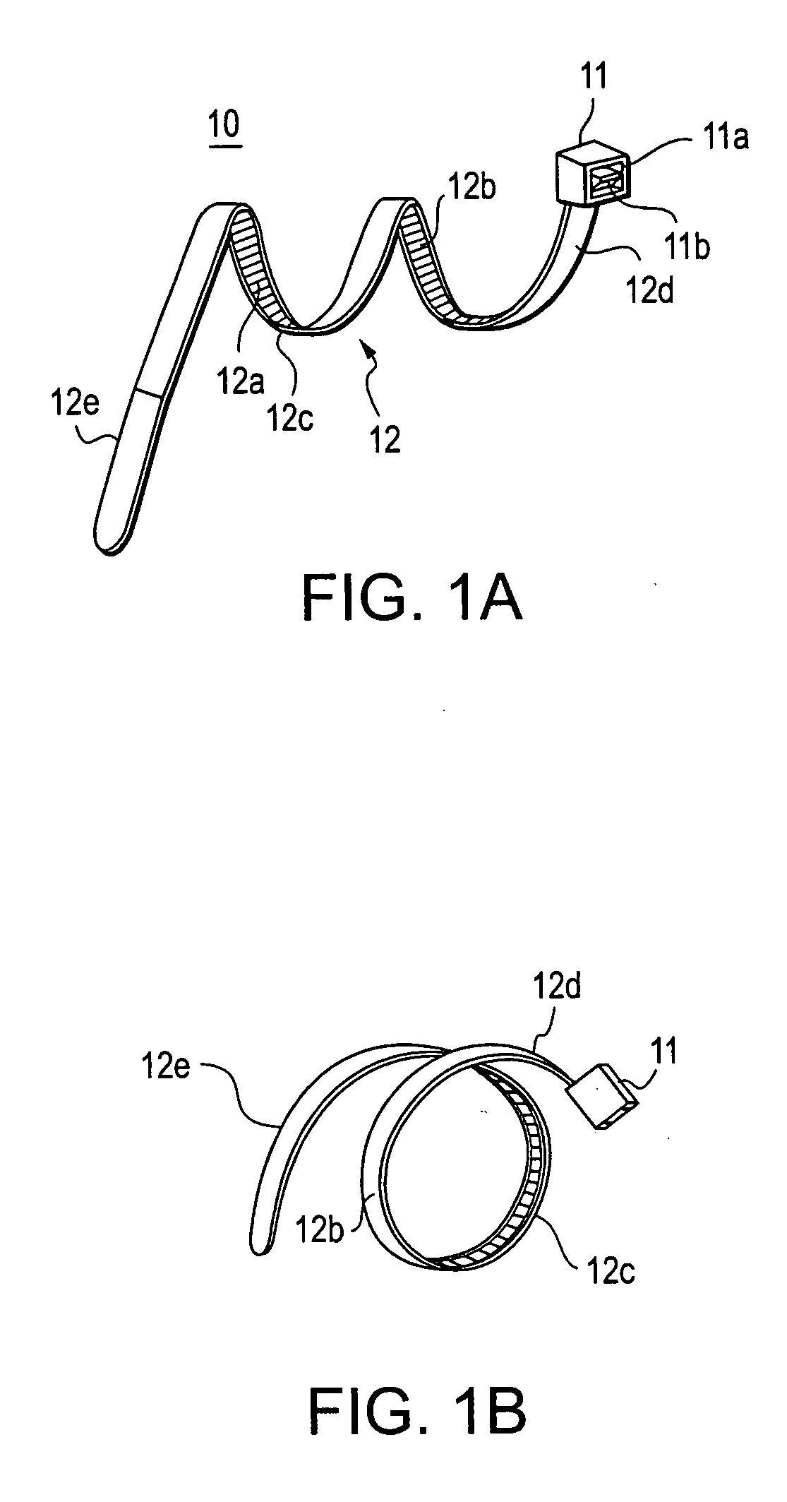
[0059] The following will explain embodiments of the invention with reference to the drawings. FIGS. 1 through 3 illustrate the invention. FIG. 1 illustrates branch wire tie band 10 (hereafter referred to as tie band 10) which may be made of any suitable material such as, for example, a synthetic resin, and in the present embodiment the resin is polypropylene. Tie band 10 includes box-shaped head portion 11 from which extends strap 12. Lock pawl 11b protrudes into lock channel 11a which is formed within head portion 11. Strap 12, onto which ratchet teeth 12a are formed, is inserted into lock channel 11a and secured at a position therein through the engagement of any of ratchet teeth 12a against lock pawl 11b.

[0060] Strap 12 is a narrow belt-shaped strap that has been formed into a spiral shape extending from head portion 11 to the tip of the strap. Half-loop shaped first and second attachment coils 12b and 12c connect to form one complete loop from which head portion side 12d conti...

third embodiment

[0072] the present invention is shown in FIGS. 12 through 14. As illustrated in FIG. 12, branch wire tie band 110 (hereafter referred to as tie band 110) includes two bands in the form of first tie band 111 and second tie band 112, and anchor plate 13. Tie bands 111 and 112 are utilitarian tie bands of identical configuration.

[0073] Anchor plate 13 is a narrow, flat, planar member of any suitable material such as, for example, resin, into which two through holes 13a and 13b are formed at the right and left ends. Tie bands 111 and 112 include straps 111a and 112a that are loosely inserted into through holes 13a and 13b which are formed to a dimension large enough to allow the inclination of straps 111a and 112a therein, but small enough to prevent head portions 111c and 112c, which are part of tie bands 111 and 112 and contain lock channels 111b and 112b formed therein, from passing there through.

[0074] Lock pawls 111e and 112e project within lock channels 111b and 112b of first and...

fourth embodiment

[0084] The procedure through which tie band 110″ is attached and wrapped around T-shaped wire branch WT has been omitted as it is identical to the attachment procedure described in the

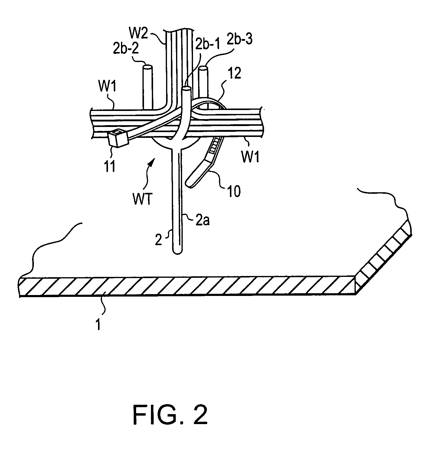
[0085] As noted previously, the present invention includes a wire branch tie band structure that includes an anchor plate in which a pair of through holes are formed, and a pair of utilitarian tie bands whose strap portions are inserted through the anchor plate through holes which are formed large enough to allow sufficient inclination of the straps therein. This structure offers a simple branch wire binding operation in which the tie bands are able to bind a branching wire location by wrapping around and mutually crossing over the trunk wires at each side of the branch wires, after which each strap is inserted and locked within the lock channel of the other tie band.

[0086] Moreover, as noted above, the procedure through which each strap is wrapped around the trunk wires at both sides of the branch wi...


PUM


Abstract

A branch wire tie band including a strap portion on which ratchet grooves are formed, the strap portion extending from a head portion within which a strap locking channel is formed. A curved attachment coil, which is preformed as an integral portion of the strap portion, is placed around the branched portion of a wire harness after which the strap portion is inserted and locked into the band locking channel. The tie band may includes two tie band strap portions extending from respective head portions and an anchor plate within which left and right through holes are formed. The two tie band straps may be inserted through the left and right through holes in the anchor plate from where they extend diagonally, their tip portions crossing, and their head portions prevented from passing through the through holes.

Description

BACKGROUND OF THE INVENTION [0001] 1. Field of the Invention [0002] The present invention relates to a tie band to tie branch wires of a wire harness, and a method of easily cross wrapping the branch wires using the tie band. [0003] 2. Description of Background Information [0004] In the prior art, a wire harness installed in a vehicle includes branch wires that lead away from the trunk wires at multiple locations. Tape is wound around the electrical wires at the branch-off points in order to secure the position of the branch wires with respect to the trunk wires. As shown in FIG. 8, the branch wires are to be tied at the point where wire bundle ‘W’ is supported by a branch jig which is mounted on wire harness assembly stand 1. Adhesive tape ‘T’ is wound around the group of wires at this location in order to bind the wires together. However, at the point where branch wires W2 separate from trunk wires W1, wire bundle ‘W’ runs between the arms of support yoke 2b′, which extends from t...

Claims


Application Information

Patent Timeline
Patent Type & Authority Applications(United States)
IPC IPC(8): B65D63/10
CPCY10T24/1498B65D63/1063
Inventor MIYAZAKI, TOMOHIROMAEDA, YOSHIHIROHIBASAMI, AKIRAUCHIDA, MIKIOYAMAUCHI, MASATAKAITO, TAKEHARUYAMAGA, KOUICHI
Owner SUMITOMO WIRING SYST LTD
Why Eureka
Try Eureka