Method and apparatus for delivery of inhaled nitric oxide to spontaneous-breathing and mechanically-ventilated patients

a technology of inhaled nitric oxide and mechanical ventilation, which is applied in the direction of mechanical equipment, valves, operating means/releasing devices, etc., can solve the problems of no toxic exposure, no toxic exposure, and limited use of blockers,

Inactive Publication Date: 2005-04-14
STENZLER ALEX
View PDF19 Cites 56 Cited by
  • Summary
  • Abstract
  • Description
  • Claims
  • Application Information

AI Technical Summary

Benefits of technology

[0023] In a first aspect of the invention a method of delivering a steady concentration of NO to a spontaneously breathing patient via delivery means is disclosed. The method includes the step of detecting the onset of inspiration by the patient. The inspiration flow profile is determined for an individual breath. An oxygen-containing g

Problems solved by technology

At high concentrations (generally at or above 1000 ppm), NO is toxic.
These drugs, such as prostacyclin, nitroprusside, hydroalazine, and calcium channel blockers suffered from the limitation that the drugs, by their nature, produced systemic effects.
First, exposure to high concentrations of NO is toxic.
NO is toxic in high concentrations, especially over 1000 ppm.
Even lower levels of NO can be harmful if the time exposure is relatively high.
Another problem with the delivery of NO is that NO rapidly oxidizes in the presence of oxygen to form NO2, which is highly toxic, even at low levels.
One problem with the inhalation of NO is that when NO is therapeutically inhaled, it is oft

Method used


Image

  • Method and apparatus for delivery of inhaled nitric oxide to spontaneous-breathing and mechanically-ventilated patients
  • Method and apparatus for delivery of inhaled nitric oxide to spontaneous-breathing and mechanically-ventilated patients
  • Method and apparatus for delivery of inhaled nitric oxide to spontaneous-breathing and mechanically-ventilated patients

Examples


Embodiment Construction

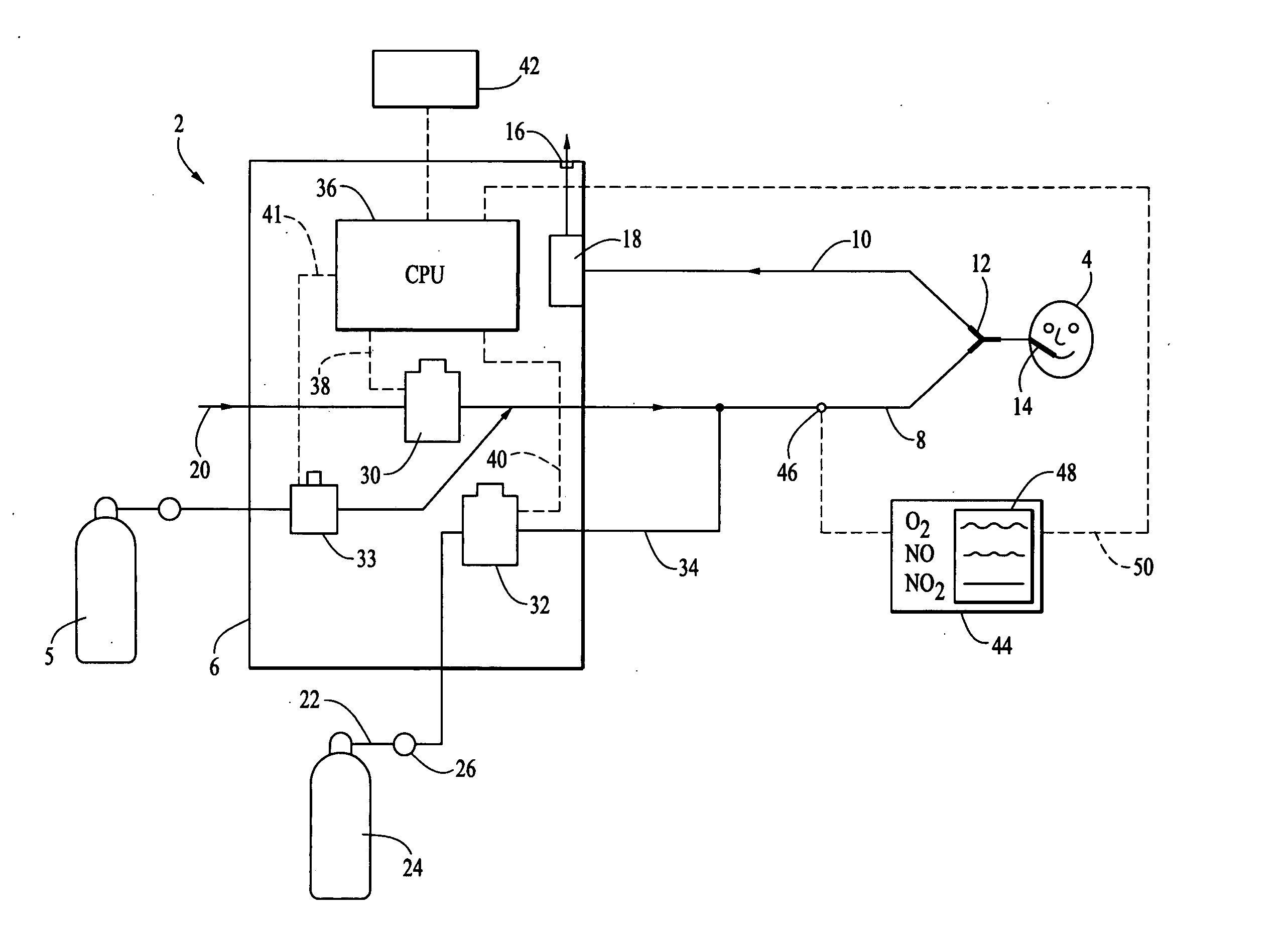
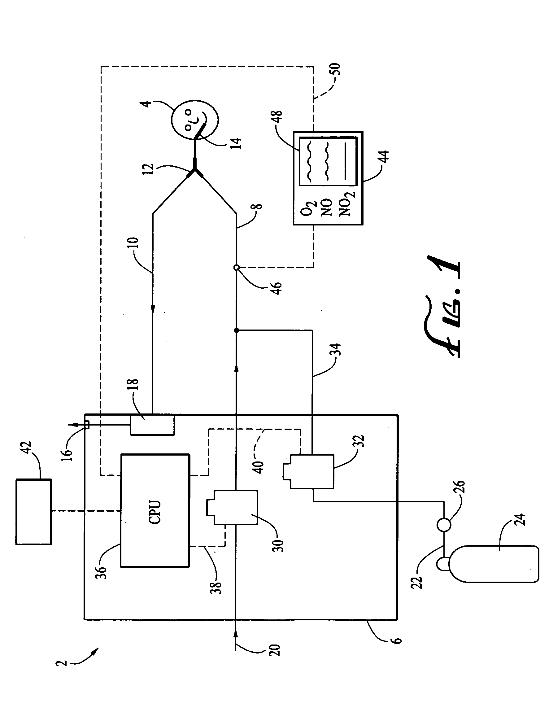
[0052] Referring now to the Figures, FIG. 1 shows a schematic representation of the device 2 for delivering NO gas to a patient 4 connected to a mechanical ventilator 6. In this embodiment of the invention, the device 2 is the mechanical ventilator 6 since both control of patient inspiration, expiration, and delivery of NO are all controlled by the device 2. In this regard, a separate NO administration device is not needed since the device 2 / mechanical ventilator 6 delivers to NO gas to the patient 4.

[0053] As seen in FIG. 1, the device 2 includes an inspiration limb 8 and an expiration limb 10. The inspiration limb 8 and the expiration limb 10 are connected via a Y-piece 12. The Y-piece 12 connects to delivery means for delivering the gaseous mixture to the patient 4. The delivery means preferably includes a patient inspiration interface device 14. The patient inspiration interface device 14 can be any number of devices that connect a generally hollow, tubular construction (i.e., ...


PUM


Abstract

A device and method is disclosed for delivering NO to a patient. The device utilizes a single controller that controls two separate flow controllers to deliver an oxygen-containing gas and a NO-containing gas to the patient. The flow profiles of the oxygen-containing gas and the NO-containing gas are controlled by the controller. In one aspect of the invention, the flow profile of the NO-containing gas is proportional to the flow profile of the oxygen-containing gas throughout patient inspiration. In this regard, the patient receives a steady concentration of NO. In another aspect of the invention, the flow profile of the NO-containing gas is quasi-proportional to the flow profile of the oxygen-containing gas. In this regard, the NO-containing gas flow profile is altered to provide an increased concentration of NO either at the beginning or end of inspiration. In one aspect, the delivery device is used with mechanically-ventilated patients. In the other aspect of the delivery device, the device is used with spontaneously-breathing patients. The device and method, in a preferred embodiment, further contemplates using a gas purge or air flush feature to remove enriched-oxygen and/or NO from the device.

Description

[0001] This application is a continuation of U.S. patent application Ser. No. 10 / 348,238 filed on Jan. 21, 2003, which is a continuation of U.S. patent application Ser. No. 09 / 449,240 issued on Jun. 24, 2003, which are hereby incorporated by reference in their entirety.[0002] The invention generally relates to an apparatus and method for measurement, mixing, monitoring, and delivery of gases to a patient, including nitric oxide (“NO”) and oxygen. More specifically, the invention relates to an apparatus and method of delivering gaseous NO to spontaneous-breathing patients as well as to patients connected to a mechanical ventilator. BACKGROUND OF THE INVENTION [0003] NO is an environmental pollutant produced as a byproduct of combustion. At high concentrations (generally at or above 1000 ppm), NO is toxic. NO also is a naturally occurring gas that is produced by the endothelium tissue of the respiratory system. In the 1980's, it was discovered by researchers that the endothelium tissu...

Claims


Application Information

Patent Timeline
IPC IPC(8): A61M16/10A61M16/12A61M16/20
CPCA61M16/12A61M2016/102A61M16/203A61M2202/0275A61M2016/1025A61M16/1015A61M16/0833A61M16/204
Inventor STENZLER, ALEX
Owner STENZLER ALEX
Why Eureka
Try Eureka