Optical disk storage case

a technology for optical disks and storage cases, applied in the direction of transportation and packaging, instruments, packaging goods, etc., can solve the problems of optical disc theft, and achieve the effect of preventing access to optical disks

Inactive Publication Date: 2005-04-14
ENXNET
View PDF99 Cites 16 Cited by
  • Summary
  • Abstract
  • Description
  • Claims
  • Application Information

AI Technical Summary

Benefits of technology

[0005] According to one embodiment of the invention, an optical disk storage case includes a base, a cover pivotally coupled to the base, a pedestal coupled to the base and having at least one pair of resilient members configured to retain an optical disc thereon, a blocking tongue coupled to a top portion of the cover and extending outwardly therefrom, and a groove associated with a top portion of the base and extending outwardly therefrom. The groove is configured to align the blocking tongue when the optical disk storage case is in a closed position and, when the pedestal is retaining the optical disk, the blocking tongue and the groove are engaged with one another such that access to the optical disk is prevented when a user slightly separates the respective top portions of the base and the cover.
[0007] Embodiments of the invention may provide a number of technical advantages. Embodiments of the invention may include all, some, or none of these advantages. In one embodiment, when a user desires to open an optical disk storage case, the user only needs to insert a finger into the latch trough at the side of the case. When opened, the base includes an penannular disk support channel including a lateral support protuberance that extends slightly above the outer edge of the optical disc. A pedestal includes cantilevered resilient arms to securely retain an optical disc. There may also be a semi-circular thumb well near the bottom of the disk support channel allowing the user to grab the edge of the optical disc in a selected position. The user applies pressure to the cantilevered resilient arms with the thumb or finger while at the same time inserting a finger or thumb into the semi-circular thumb well, thereby releasing the optical disc from the pedestal.

Problems solved by technology

The most prevalent problem with such a disc box structure is theft of the optical disc.

Method used


Image

  • Optical disk storage case
  • Optical disk storage case
  • Optical disk storage case

Examples


Embodiment Construction

[0015] Example embodiments of the present invention are best understood by referring now to FIGS. 1 through 4 of the drawings, in which like numerals refer to like parts.

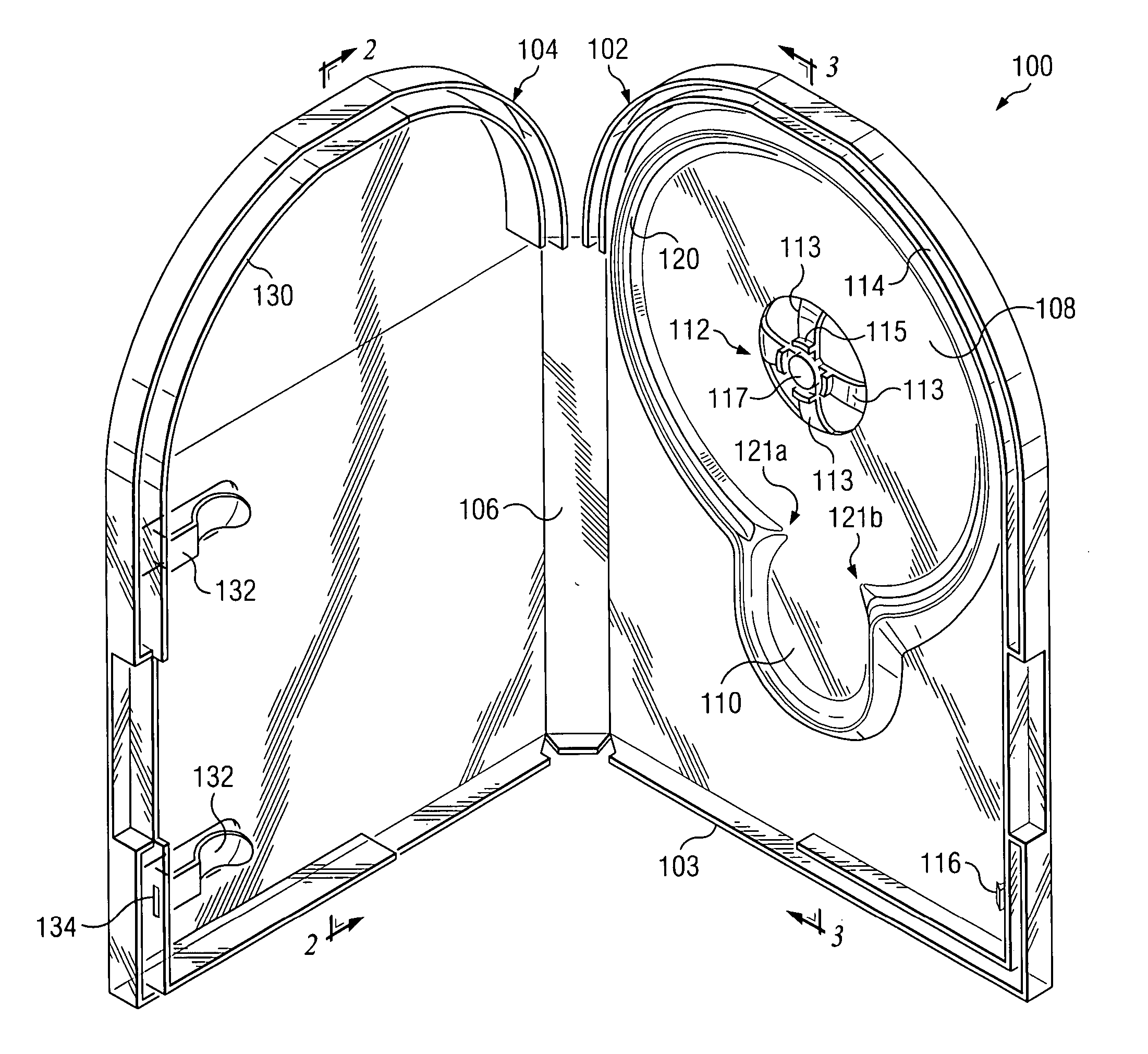
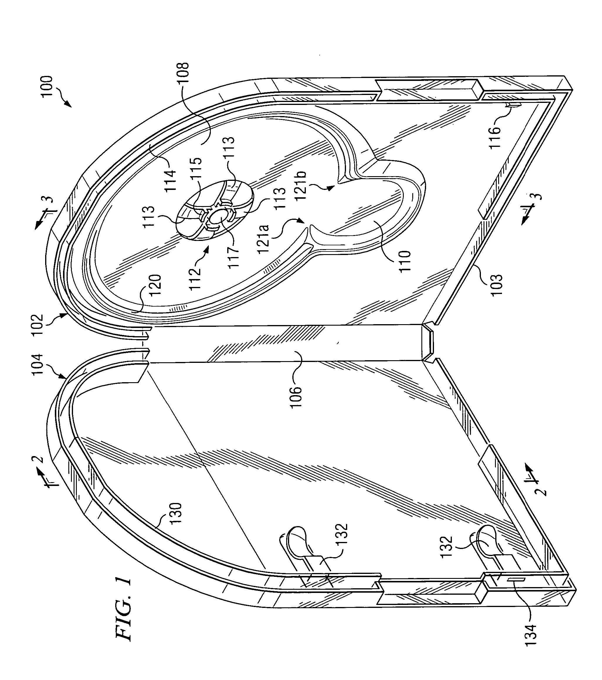
[0016]FIG. 1 is a perspective view of an optical disk storage case 100 shown in an open position according to one embodiment of the present invention. Although optical disk storage case 100 is discussed herein in the context of housing compact disks (“CDs”) and digital versatile disks (“DVDs”), the present invention contemplates optical disk storage case 100 housing any suitable object. Optical disk storage case 100 may be formed from any suitable material. For example, optical disk storage case 100 may be formed from a suitable polymer, such as polypropylene. In addition, optical disk storage case 100 may have any suitable configuration with any suitable dimensions.

[0017] In the illustrated embodiment, optical disk storage case 100 includes a base 102 and a cover 104 pivotally coupled to base 102 by a hinge porti...


PUM

PropertyMeasurementUnit
resilientaaaaaaaaaa
radiusaaaaaaaaaa
transparentaaaaaaaaaa

Abstract

According to one embodiment of the invention, an optical disk storage case includes a base, a cover pivotally coupled to the base, a pedestal coupled to the base and having at least one pair of resilient members configured to retain an optical disc thereon, a blocking tongue coupled to a top portion of the cover and extending outwardly therefrom, and a groove associated with a top portion of the base and extending outwardly therefrom. The groove is configured to align the blocking tongue when the optical disk storage case is in a closed position and, when the pedestal is retaining the optical disk, the blocking tongue and the groove are engaged with one another such that access to the optical disk is prevented when a user slightly separates the respective top portions of the base and the cover.

Description

RELATED APPLICATIONS [0001] This application claims the benefit of Ser. No. 60 / 510,384 titled “Optical Disk Storage Device,” filed provisionally on Oct. 10, 2003.FIELD OF THE INVENTION [0002] This invention relates generally to storage systems for optical disks, such as compact discs (“CDs”) and digital versatile discs (“DVDs”), and, more particularly, to an optical disk storage case. BACKGROUND OF THE INVENTION [0003] Optical disks, such as CDs and DVDs, are increasingly popular with today's consumers. Because of the nature and cost of optical disks, their storage is important with respect to both protection and theft prevention. Conventional plastic packaging and vacuum molded cases for DVD's and CD's have been on the market for several years. The majority of the commercial storage cases on the market today consist of a vacuum molded case. A common disc storage case includes a box body, a cover body pivotally connected to one side of the box body, a rectangular peripheral frame be...

Claims


Application Information

Patent Timeline
Patent Type & Authority Applications(United States)
IPC IPC(8): B65DB65D85/57G11B33/04
CPCG11B33/0427
Inventor CORLEY, RYANPEMPSELL, MARK
Owner ENXNET
Why Eureka
Try Eureka