Common reference target machine vision wheel alignment system

a technology of machine vision and alignment system, which is applied in the direction of instruments, measurement devices, surveying and navigation, etc., can solve the problems of impracticality of a single rigid support structure which is sufficiently large so as to dispose cameras in operative positions to view both the left and right sides of the vehicle, and becomes impractical

Active Publication Date: 2005-04-14
HUNTER ENG
View PDF24 Cites 37 Cited by
  • Summary
  • Abstract
  • Description
  • Claims
  • Application Information

AI Technical Summary

Benefits of technology

[0010] Briefly stated, the present invention sets forth a multi-camera configuration for a machine vision vehicle wheel alignment system which does not dispose all of the cameras on a single rigid structure, such that one or more cameras d...

Problems solved by technology

For some applications and installations of machine vision vehicle wheel alignment systems, the utilization of a single rigid support structure which is sufficiently large so as to dispose cameras in operative positions to view both the left and r...

Method used


Image

  • Common reference target machine vision wheel alignment system
  • Common reference target machine vision wheel alignment system
  • Common reference target machine vision wheel alignment system

Examples


Embodiment Construction

[0024] The following detailed description illustrates the invention by way of example and not by way of limitation. The description clearly enables one skilled in the art to make and use the invention, describes several embodiments, adaptations, variations, alternatives, and uses of the invention, including what is presently believed to be the best mode of carrying out the invention.

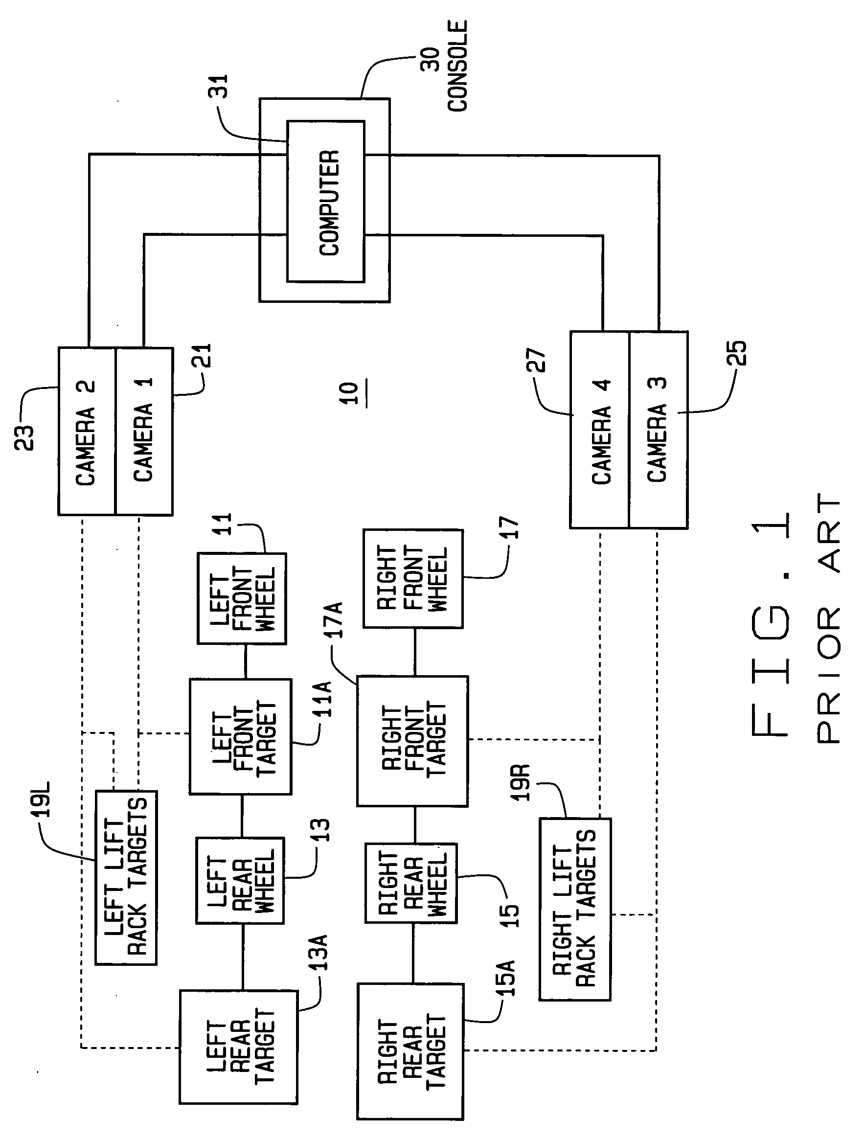
[0025] Turning to FIG. 1, the basic components of a conventional machine vision vehicle wheel alignment system, such as the Series 811 Aligner with the DSP600 sensors from Hunter Engineering Co. of Bridgeton, Mo. are shown generally at 10. The system 10 is configured to determine the position and orientation of vehicle wheels 11, 13, 15, and 17, and the axis about which they roll. Each vehicle wheel has associated therewith one or more optical targets 11A, 13A, 15A, and 17A. Optionally, additional optical targets such as 19L and 19R may be associated with the two sides of a runway or other support struc...


PUM


Abstract

A camera configuration for a machine vision vehicle wheel alignment system which does not dispose all of the cameras on a single rigid structure, such that cameras disposed to view the left side of a vehicle are movable independently of the cameras disposed to view the right side of the vehicle, while maintaining a common reference coordinate system for determining vehicle wheel alignment angles.

Description

CROSS-REFERENCE TO RELATED APPLICATIONS [0001] Not Applicable. STATEMENT REGARDING FEDERALLY SPONSORED RESEARCH [0002] Not Applicable. BACKGROUND OF THE INVENTION [0003] The present invention relates to machine vision vehicle wheel alignment systems configured to measure the locations and orientation of the vehicle wheels in a three dimensional coordinate system, and more particularly, to configurations of machine vision cameras and optical targets disposed about a vehicle undergoing an alignment inspection. [0004] Machine vision vehicle wheel alignment systems have been in use by the vehicle service industry for several years. A typical machine vision vehicle wheel alignment system, such as the Series 811 wheel alignment system, configured with the DSP600 sensors manufactured by Hunter Engineering Co. of Bridgeton, Mo. consists of a console unit, cameras, and optical targets. The console unit contains a computer configured with image processing and vehicle wheel alignment software ...

Claims


Application Information

Patent Timeline
IPC IPC(8): G01B11/275G01C11/04
CPCG01C11/04G01B11/275
Inventor DORRANCE, DANIEL R.STREGE, TIMOTHY A.BURNS, LEIGH R. JR.SHYLANSKI, MARK S.GOLAB, THOMAS J.
Owner HUNTER ENG
Why Eureka
Try Eureka