
Recording control apparatus, recording and reproduction apparatus, and recording control method

a recording control and recording control technology, applied in the field of recording control apparatus, recording and reproduction apparatus, recording control method, can solve the problem of significant difference in the quality of the signal reproduced, and achieve the effect of minimal probability of error generation at the time of maximum likelihood decoding

Active Publication Date: 2005-04-14
PANASONIC CORP
View PDF6 Cites 33 Cited by
  • Summary
  • Abstract
  • Description
  • Claims
  • Application Information

AI Technical Summary

Benefits of technology

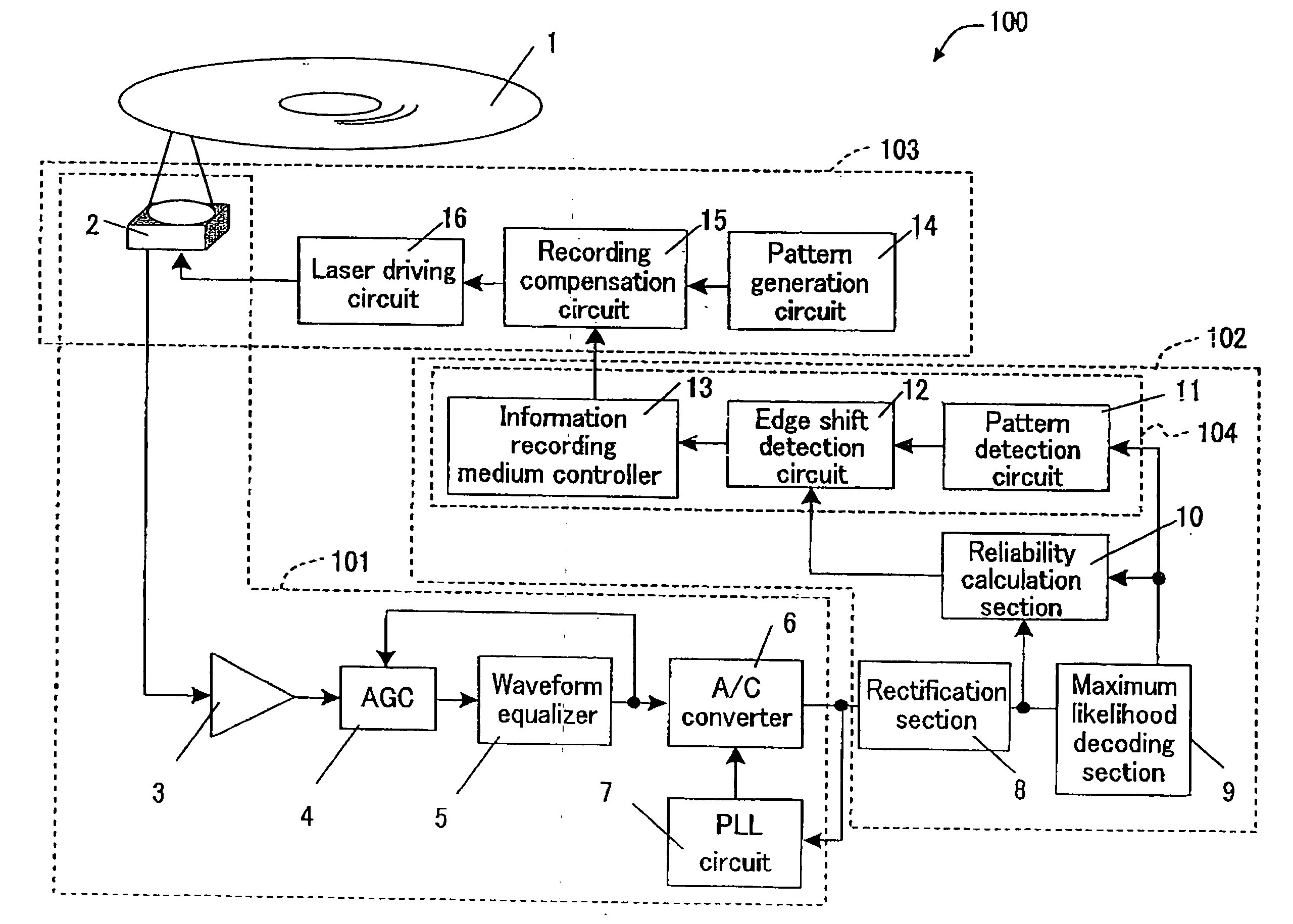
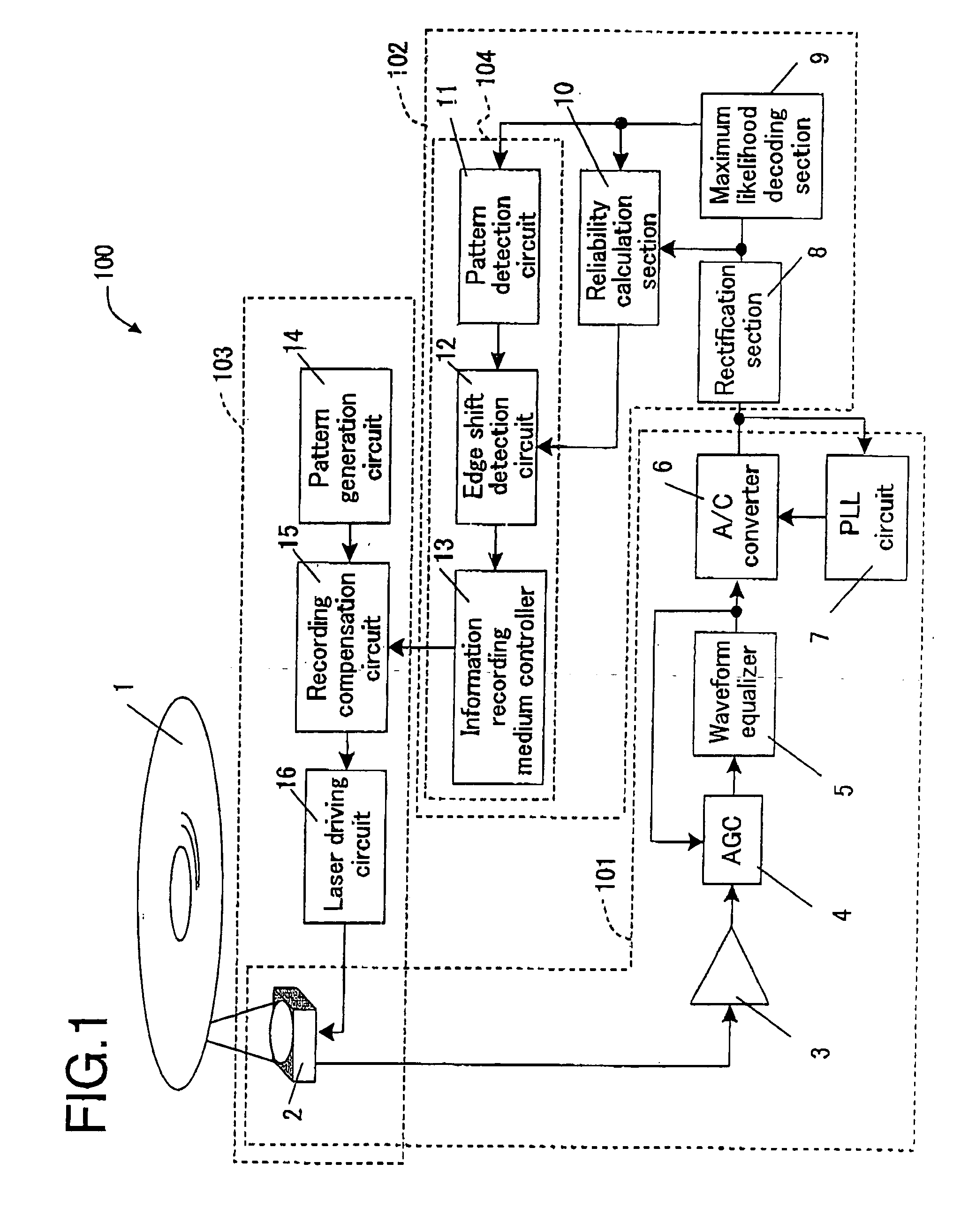
In one embodiment of the invention, the adjusting section adjusts the shape of the recording signal so as to improve the reliability.
According to still another aspect of the invention, a recording control method includes the steps of receiving a digital signal generated from an analog signal representing information reproduced from an information recording medium, and rectifying a waveform of the digital signal; performing maximum likelihood decoding of the digital signal having the waveform thereof rectified, and generating a binary signal representing a result of the maximum likelihood decoding; calculating a reliability of the result of the maximum likelihood decoding based on the digital signal having the waveform thereof rectified and the binary signal; and adjusting a shape of a recording signal for recording the information on the information recording medium based on the calculated reliability.
Thus, the invention described herein makes possible the advantages of providing a recording control apparatus, a recording and reproduction apparatus, and a recording control method for optimizing a recording parameter when recording information, such that the probability of error generation at the time of maximum-likelihood decoding is minimal.

Problems solved by technology

This results in significant difference in the quality of the signal reproduced.

Method used


Image

  • Recording control apparatus, recording and reproduction apparatus, and recording control method
  • Recording control apparatus, recording and reproduction apparatus, and recording control method
  • Recording control apparatus, recording and reproduction apparatus, and recording control method

Examples


Embodiment Construction

Hereinafter, the present invention will be described by way of illustrative examples with reference to the accompanying drawings.

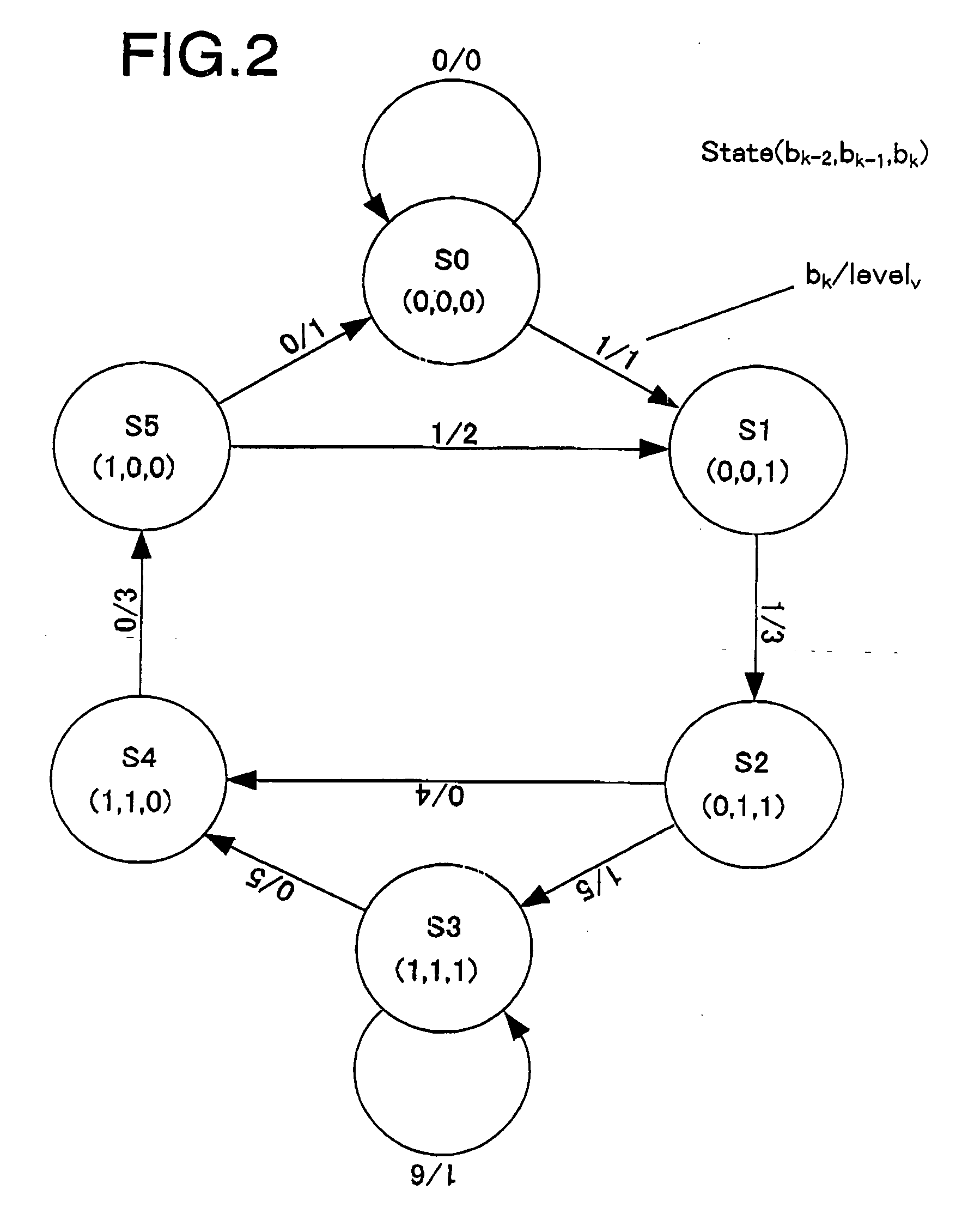
First, a method for evaluating the quality of a reproduction signal obtained by using a maximum likelihood decoding method will be described. In the following example, a recording symbol having a minimum polarity inversion interval of 2 is used, and the waveform of the signal is rectified such that the frequency characteristic of the signal at the time of recording and reproduction matches PR (1, 2, 2, 1).

Where the instant recording symbol is bk, the immediately previous recording signal is bk−1, the recording signal two times previous is bk−2, and the recording signal three times previous is bk−3, an ideal output value Levelv matching PR (1,2,2,1) is represented by expression 1.

Levelv=bk−3+2bk−2+2bk−1+bk  expression 1 where k is an integer representing the time, and v is an integer of 0 through 6.

Where the state at time k is S(bk−2, bk−1, bk), th...


PUM


Abstract

A recording control apparatus includes a waveform rectification section for receiving a digital signal generated from an analog signal representing information reproduced from an information recording medium, and rectifying a waveform of the digital signal; a maximum likelihood decoding section for performing maximum likelihood decoding of the digital signal having the waveform thereof rectified, and generating a binary signal representing a result of the maximum likelihood decoding; a reliability calculation section for calculating a reliability of the result of the maximum likelihood decoding based on the digital signal having the waveform thereof rectified and the binary signal; and an adjusting section for adjusting a shape of a recording signal for recording the information on the information recording medium based on the calculated reliability.

Description

This non-provisional application claims priority under 35 U.S.C., §119(a), on Patent Application No. 2003-108821 filed in Japan on Apr. 14, 2003, the entire contents of which are hereby incorporated by reference. BACKGROUND OF THE INVENTION 1. Field of the Invention The present invention relates to a recording control apparatus, a recording and reproduction apparatus, and a recording control method using a maximum likelihood decoding method. 2. Description of the Related Art In recording and reproduction apparatuses for recording original digital information on, or reproducing such information from, a portable recording medium, there can be a variance in the shape of marks formed on the medium among individual apparatuses or recording mediums even with an identical shape of recording pulse. This results in significant difference in the quality of the signal reproduced. In order to avoid reduction in the reliability due to the variance, a correction operation is performed when, ...

Claims


Application Information

Patent Timeline
IPC IPC(8): G11B20/10G11B20/14
CPCG11B7/00456G11B7/0062G11B20/10009G11B20/1403G11B20/10111G11B20/10481G11B20/10055G02F1/133606G02F1/133604G02F1/133605G02F1/133611G02F1/133607
Inventor MIYASHITA, HARUMITSUNAKAJIMA, TAKESHIKIMURA, NAOHIRO
Owner PANASONIC CORP
Learn More