Quantum cryptography communication system and quantum cryptography key distributing method used in the same
a quantum cryptography and communication system technology, applied in the direction of secret communication, synchronising transmission/receiving encryption devices, digital transmission, etc., can solve the problems of limited distance between the base stations between which cryptography communication can be carried out, and the end-of-encrypted data could be finally decrypted
- Summary
- Abstract
- Description
- Claims
- Application Information
AI Technical Summary
Problems solved by technology
Method used
Image
Examples
first embodiment
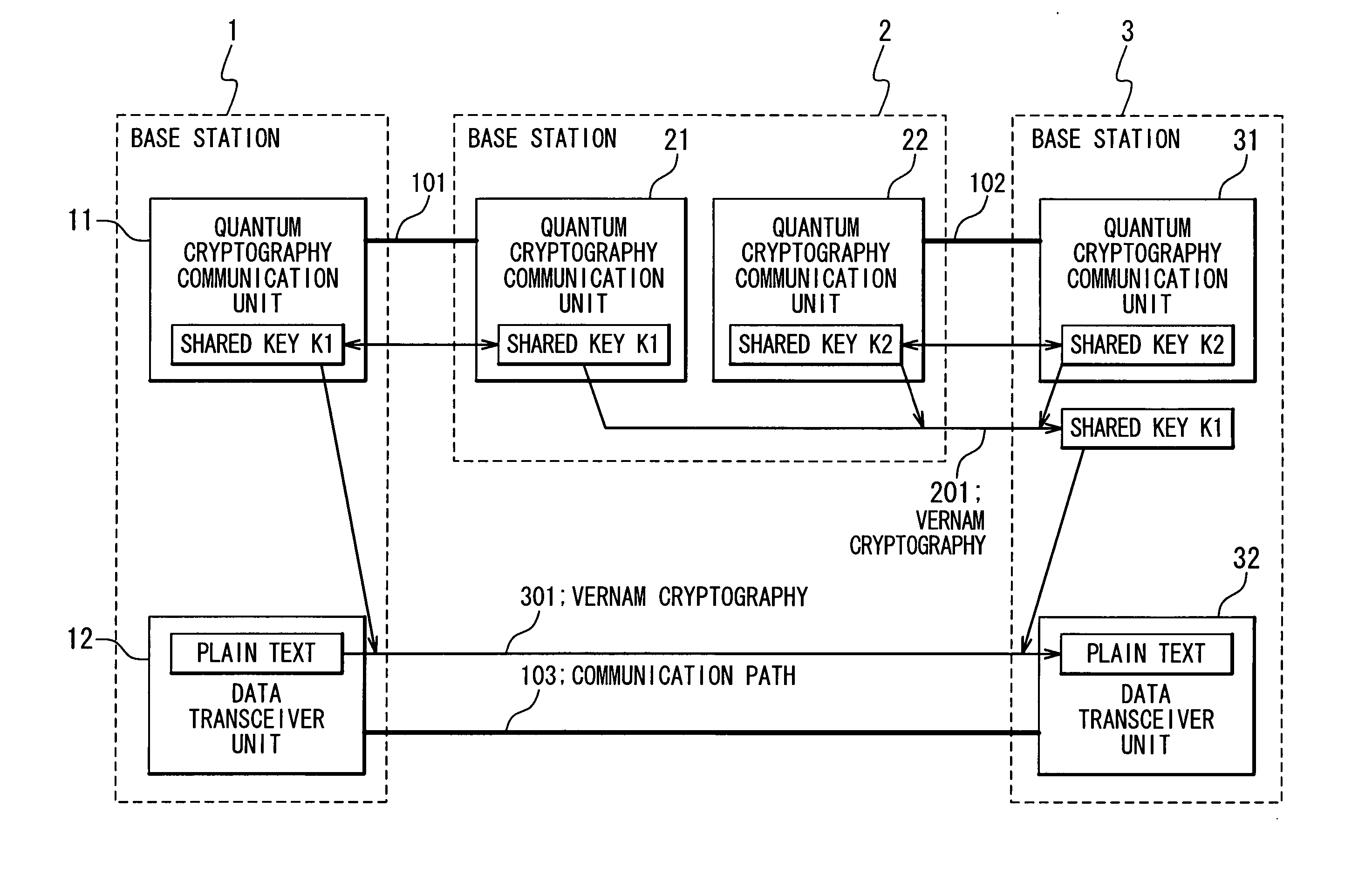
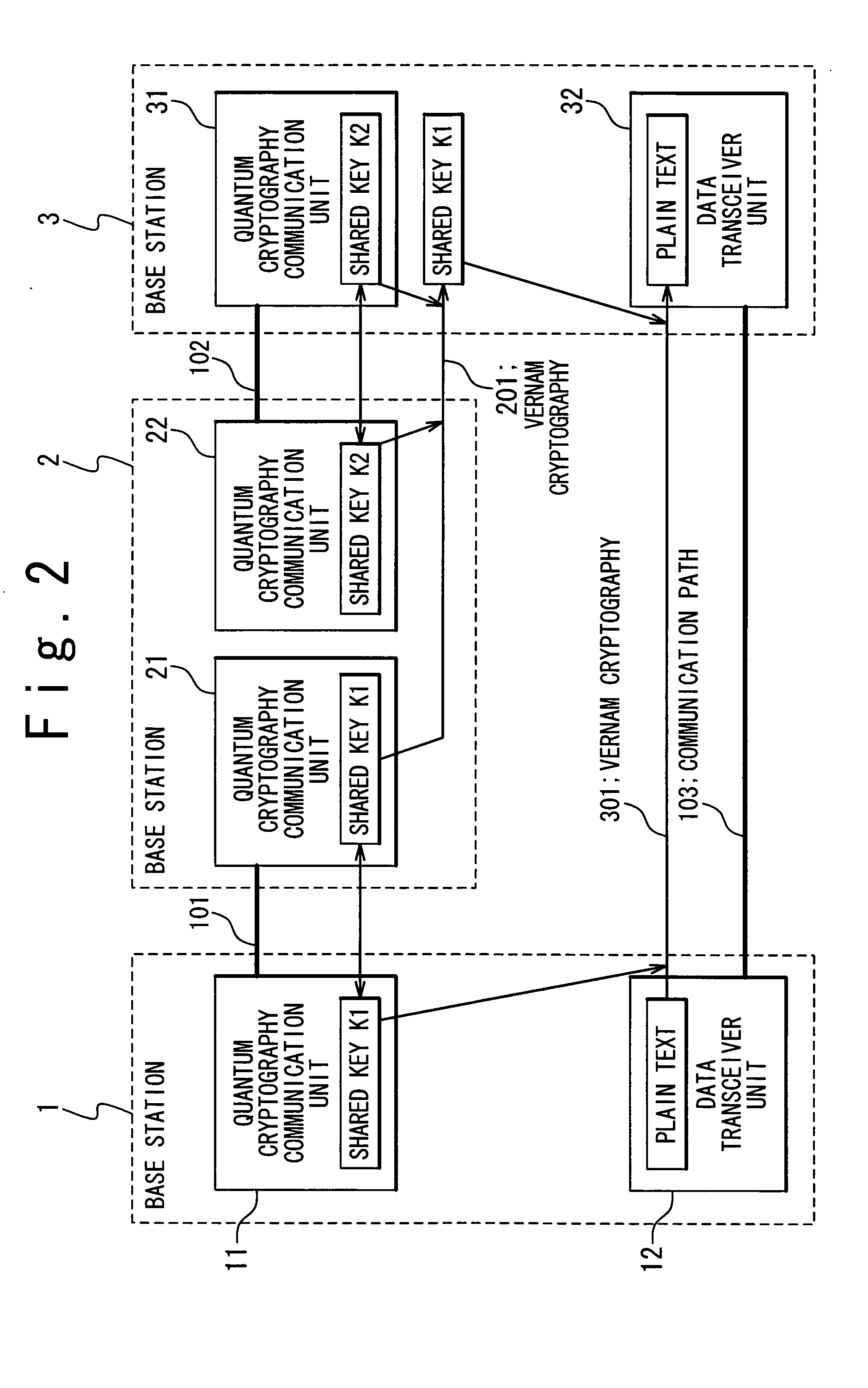
[0047]FIG. 3 is a sequence chart showing distributions of the quantum cryptography shared keys in the quantum cryptography communication system according to the present invention. First, a quantum cryptography shared key “K1” is generated (a1 of FIG. 3) between the base station 1 and the base station 2, and another quantum cryptography shared key “K2” is generated (a2 of FIG. 3) between the base station 2 and the base station 3 in accordance with the above-mentioned quantum cryptography protocol.
[0048] Subsequently, the base station 2 encrypts the quantum cryptography shared key “K1” by using the quantum cryptography shared key “K2” to produce a Vernam cryptograph 201, and then transmits the Vernam cryptograph 201 to the base station 3 on the optical fiber 102 (a4 of FIG. 3).
[0049] In the base station 3, since the Vernam cryptograph 201 transmitted from the base station 2 is decrypted by using the quantum cryptography shared key “K2”, the quantum cryptography shared key “K1” is obt...
second embodiment
[0057] As a consequence, in this second embodiment, the quantum cryptography shared key “K1” can be distributed from the base station 1 to the base station N, while the base stations 2 to N−1 are employed as the relay points, and a distance between the base station 1 and the base station N is longer than or equal to 100 Km.
[0058]FIG. 6 is a schematic block diagram showing the configuration of the quantum cryptography communication system according to the third embodiment of the present invention. In FIG. 6, in the quantum cryptography communication system according to the third embodiment of the present invention, quantum cryptography shared keys “K1A” and “K1B” are distributed from a base station 1 to a base station 3 and a base station 4, respectively, by using a base station 2 as a relay point to transfer / relay these shared keys “K1A” and “K1B.”
[0059] In this quantum cryptography communication system, the base station 1 is connected to the base station 2 by an optical fiber 101, ...
third embodiment
[0060]FIG. 7 is a sequence chart showing distributions of quantum cryptography shared keys in the quantum cryptography communication system according to the present invention. Referring now to FIG. 6 and FIG. 7, the quantum cryptography communication unit 13 of the base station 1 generates quantum cryptography shared keys “K1A” and “K1B” based upon the quantum cryptography protocol with respect to the base station 2 (c1 and c2 of FIG. 7), the quantum cryptography communication unit 24 of the base station 2 generates quantum cryptography shared key “K23” with respect to the base station 3 and a quantum cryptography shared key “K24” with respect to the base station 4 based upon the quantum cryptography protocol (c3 and c4 of FIG. 7).
[0061] Subsequently, the base station 2 encrypts the quantum cryptography shared key “K1A” by using the quantum cryptography shared key “K23” to produce a Vernam cryptograph 202 (c5 of FIG. 7), and then transmits this Vernam cryptograph 202 to the base sta...
PUM
 Abstract
Description
Claims
Application Information
 - R&D
- Intellectual Property
- Life Sciences
- Materials
- Tech Scout
- Unparalleled Data Quality
- Higher Quality Content
- 60% Fewer Hallucinations
Browse by: Latest US Patents, China's latest patents, Technical Efficacy Thesaurus, Application Domain, Technology Topic, Popular Technical Reports.
© 2025 PatSnap. All rights reserved.Legal|Privacy policy|Modern Slavery Act Transparency Statement|Sitemap|About US| Contact US: help@patsnap.com


