Image forming apparatus

a technology of image forming apparatus and forming machine, which is applied in the direction of instruments, printing mechanisms, electrographic processes, etc., can solve the problems of inability to achieve image quality improvement in the end, users are reluctant to make such settings, and users do not know how to handle or use the apparatus

Inactive Publication Date: 2005-04-14
RICOH KK
View PDF6 Cites 64 Cited by
  • Summary
  • Abstract
  • Description
  • Claims
  • Application Information

AI Technical Summary

Problems solved by technology

Nevertheless, in offices, shops, or the like where the image forming apparatus includes multiple tiers of paper feed trays and many unspecified users use various types of paper for the apparatus, the users are reluctant to make such settings as it is complicated, and some users do not know how to handle or how to use the apparatus.
Therefore, improvements on image quality cannot be attained in the end.
With each of the conventional techniques, the apparatus can identify only specific items and cannot detect the characteristics of the paper which can be recognized only after two pieces of information, i.e., transmittance and reflectance are detected.
As a result, a disadvantage that the transfer device, the fixing device, and the like cannot be controlled based on these pieces of information occurs to the apparatus.
As a result, the apparatus erroneously determines the thickness of the paper as thicker than the actual thickness.

Method used


Image

  • Image forming apparatus
  • Image forming apparatus
  • Image forming apparatus

Examples


Embodiment Construction

[0034] Exemplary embodiments of the present invention are explained in detail below with reference to the accompanying drawings.

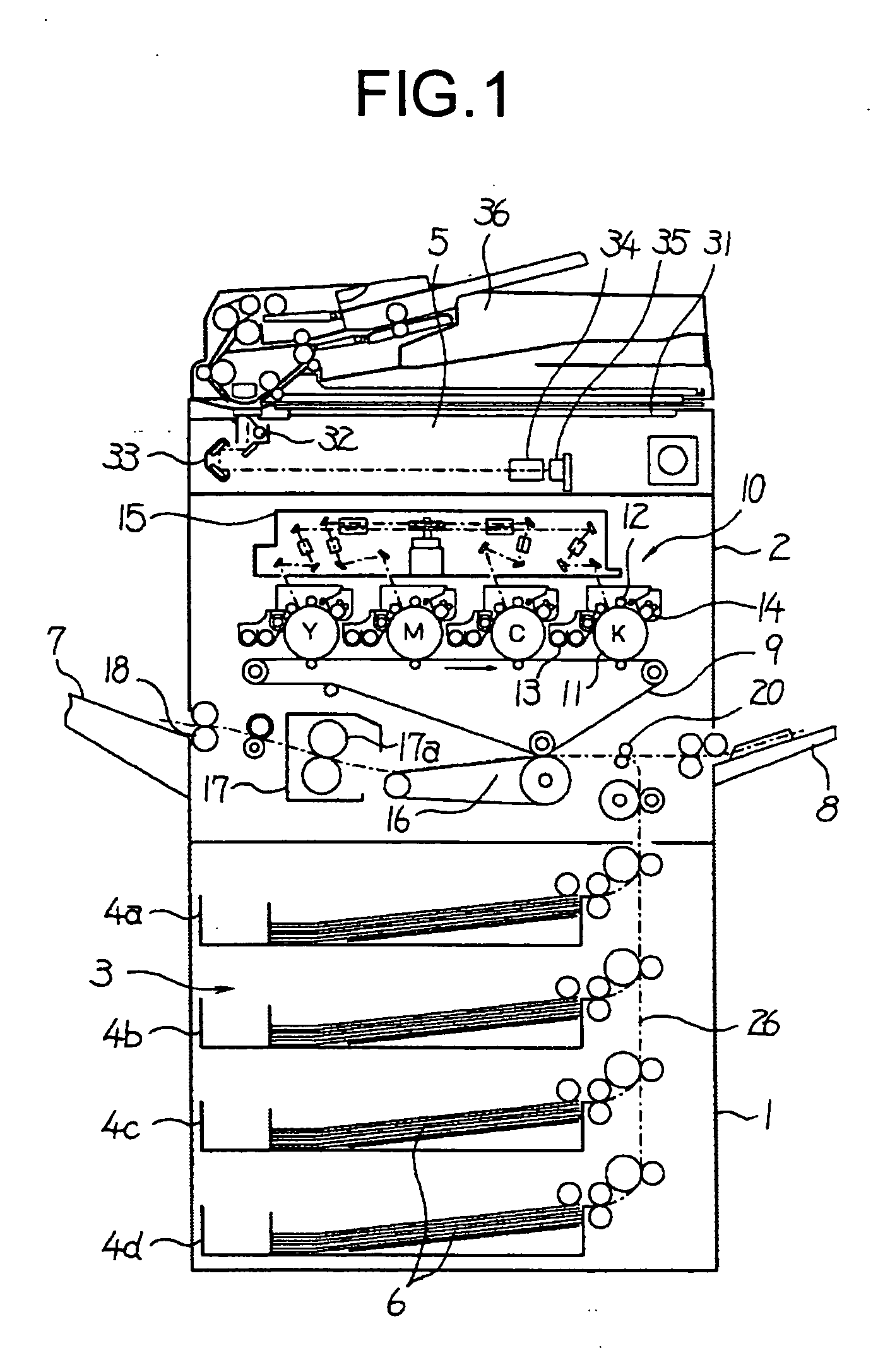
[0035] An instance in which a tandem-type full color image forming apparatus using electrophotography is used as an image forming apparatus according to the embodiment of the present invention will be explained herein. FIG. 1 is a longitudinal front view of the overall schematic configuration of the full color image forming apparatus. In an apparatus main unit 1, an image forming unit (a printer engine) 2 is provided generally at a center, and a paper feed unit 3 serving as a paper feeder is arranged just under the image forming unit 2. The paper feed unit (paper supply unit) 3 includes paper feed cassettes 4a to 4d of four-tier, each serving as, for example, a paper storage unit. The paper feed units 4a to 4d are provided to be freely pulled out from and contained in the apparatus main unit in a longitudinal direction (a direction from a front surface to ...


PUM


Abstract

An image forming apparatus has a printer engine which forms an image on a medium; a unit which supplies the medium to the engine through a path; an element which emits light onto the medium at a position on the path; a receiving element which receives transmitted light of the light emitted which is transmitted through the medium; another receiving element which receives reflected light of the light emitted which is reflected by the medium; a unit which executes a detection through the emission and reception; a unit which determines a characteristic of the medium based on detection signals output by the receiving elements as a result of the detection; and a control unit which executes a control in the apparatus based on the characteristic.

Description

CROSS-REFERENCE TO RELATED APPLICATIONS [0001] The present document incorporates by reference the entire contents of Japanese priority document, 2003-301275 filed in Japan on Aug. 26, 2003. BACKGROUND OF THE INVENTION [0002] 1) Field of the Invention [0003] The present invention relates to an image forming apparatus that forms an image on a medium such as paper. [0004] 2) Description of the Related Art [0005] Japanese Patent Application Laid-Open No. 07-196207 discloses a technique for allowing an optical projector and an optical receiver which form an optical axis that crosses a print paper drawn out from a paper feed tray to detect a quantity of light transmitted through the print paper, converting the detected quantity of transmitted light into a corresponding voltage, comparing the voltage corresponding to the quantity of transmitted light with a predetermined threshold, and determining a type of the print paper. The determination result is then transmitted to a host computer. [...

Claims


Application Information

Patent Timeline
Patent Type & Authority Applications(United States)
IPC IPC(8): B41J25/308B65H7/14G03G15/00G03G21/00
CPCB65H7/14B65H2511/13G03G2215/00738G03G15/5029B65H2557/61B65H2553/44B65H2553/414B65H2553/412B65H2515/60B65H2511/51B65H2220/03B65H2220/01B65H2220/02
Inventor SUZUKI, NOBUTAKA
Owner RICOH KK
Why Eureka
Try Eureka