Positioning apparatus for container forming machine

a technology for forming machines and containers, which is applied in the field of forming containers, can solve the problems of large behemoths requiring considerable floor space, unable to effectively utilize the floor space of neither machine, and achieve the effect of reducing the overall footprint of the machin

Inactive Publication Date: 2005-04-14
MOSHIER JAMES +2
View PDF15 Cites 5 Cited by
  • Summary
  • Abstract
  • Description
  • Claims
  • Application Information

AI Technical Summary

Benefits of technology

[0012] The present invention provides an apparatus for use in a container forming machine that alters the path of a partially-formed container in a particular direction while rotating the container itself to a selected angle or position. The apparatus may be incorporated into any container forming machine as an alternative to a traditional unidirectional conveying means. In one embodiment, the apparatus of the present invention allows the path of container formation inside the machine to double back against itself in a U-turn (180 degrees), thereby reducing the overall footprint of the machine, while at the same time positioning the partially-formed container for further formation activity by rotating the container itself only 90 degrees.
[0017] Accordingly, it is possible to use the present invention to minimize the floor space requirements of any container assembly device by providing up to a 180 degree turn in the path of assembly. A 180 degree turn provides the greatest potential reduction in the physical dimension of the overall machine, in that instead of a single lengthy straight path of formation, the path doubles back against itself making for a more compact machine. The floor space requirements may be further optimized using several 180 degree turns within the same conveying means. Finally, the use of a single base plate with multiple rotatable support arms provides improved throughput as well as a simple and effective alternative to earlier inventions.
[0018] It is therefore a primary object of the present invention to provide an apparatus for use in a container forming machine that alters the path of container formation for optimal results.
[0019] It is also a primary object of the present invention to provide an apparatus for use in a container forming machine that alters the path of container formation so as to minimize the physical dimensions of the overall machine, and permit the formation of containers in locations having minimal available floor space.
[0021] It is a further object of the present invention to provide an apparatus for turning the path of formation in a container forming machine which minimizes unused floor space by making full and efficient use of the floor space bounded within the container conveying means.
[0022] Finally, it is also an important object of the present invention to provide an apparatus for changing the path of formation in a container forming machine which is relatively simple to implement, adjust and maintain.

Problems solved by technology

In many instances, the addition of multiple desirable features on such machines transforms the machines into large behemoths requiring considerable floor space within a warehouse or packing facility for proper operation.
Such a device requires significant floor space, since its length must accommodate all three stations adjacent to each other.
Unfortunately, neither of these machines effectively utilizes its floor space.
This actually results in a greater floor space requirement, since the empty rectangular floor space partially bounded by the conveying means has limited uses.
Specifically, usage of such empty space is limited by safety concerns, the need for routine service of, and access to, the device, and the availability of other devices that would fit within the empty space.
The remaining unused floor space is not easily accessible from outside the bounded conveying means, and is therefore wasted.
An alternatively shaped fitment shape would prevent the container from rotating while being grasped by machine, and using symmetrical or circular fitments would creating a risk that the containers would not be properly rotated during the turn.

Method used


Image

  • Positioning apparatus for container forming machine
  • Positioning apparatus for container forming machine
  • Positioning apparatus for container forming machine

Examples


Embodiment Construction

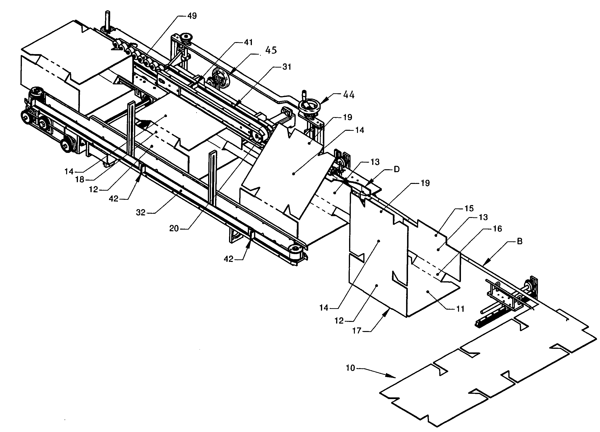
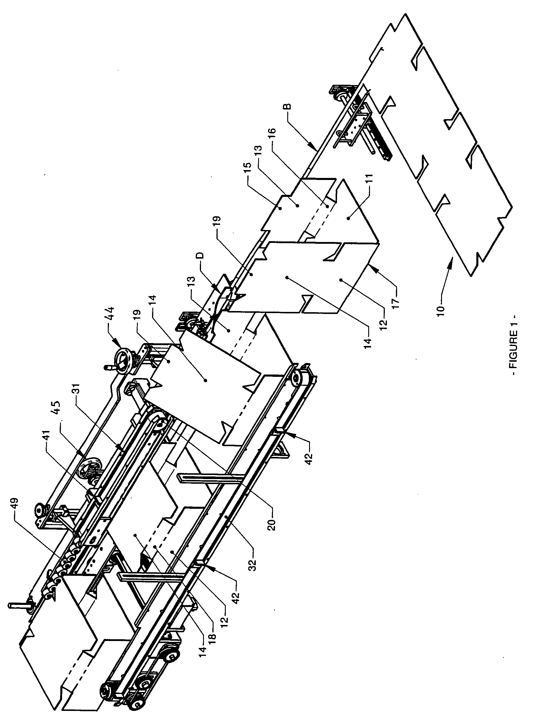
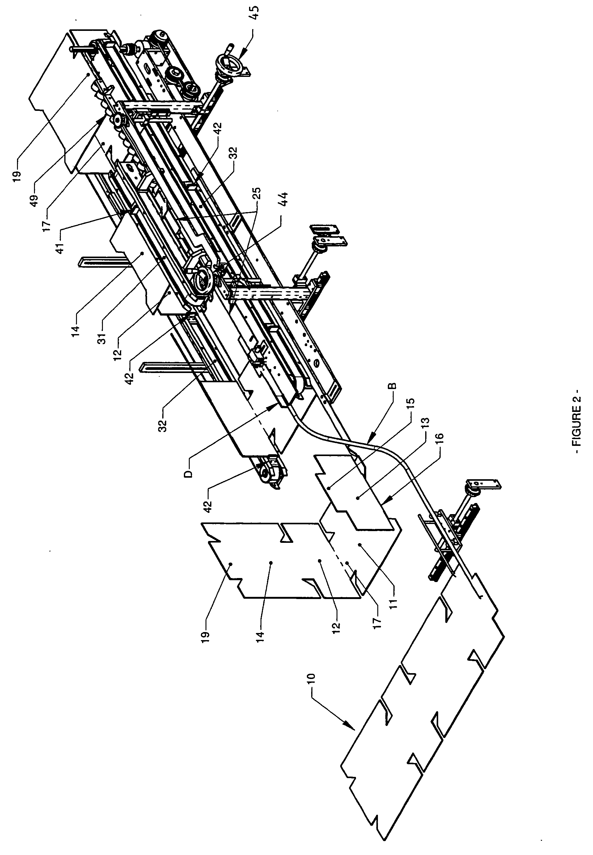
[0036] Referring to the drawings wherein like reference characters designate like or corresponding parts throughout the several views, and referring particularly to FIG. 1 it is seen that the illustrated formation apparatus includes a series of plows and guides which bend, fold and wrap the plurality of panels of a container blank 10 to form the body of a container as the blank 10 is fed laterally through a forming machine. It is to be appreciated that the blank 10 illustrated in FIGS. 1-2 and 4-6 has eight panels such that it forms an octagonal container body, but that a blank 10 having any number of panels (e.g., 4-12, or more) could also be formed in a similar manner with minor adjustments to the plows and guides of the machine.

[0037] In the example illustrated in FIG. 4, blank 10 is urged forward laterally through the machine by the primary conveyors 22. The exemplary embodiment of FIGS. 4 and 7 illustrates primary conveyors 22 as a pair of pinch belts 22 and 23, however it is ...


PUM


Abstract

The present invention provides an apparatus for use in a container forming machine that alters the path of a partially-formed container in a particular direction while independently rotating the partially-formed container itself to a selected angle or position. The apparatus may be incorporated into any container forming machine as an alternative to the traditional unidirectional conveying means. In one embodiment, the apparatus of the present invention allows the path of container formation inside the machine to double back against itself in a U-turn (180 degrees), thereby reducing the overall footprint of the machine, while at the same time positioning the partially-formed container for further formation activity by rotating the container itself only 90 degrees. In another embodiment, an apparatus is provided that raises or opens the partially-formed container as it travels along the altered path.

Description

BACKGROUND OF THE INVENTION [0001] 1. Field of the Invention [0002] The present invention relates to machines for forming containers from flat paperboard blanks, and more particularly to an apparatus in such a machine that allows the path of container formation inside the machine to be altered (turned) so as to optimize the overall dimensional profile of the machine, while also rotating containers being formed to a desired angle for further processing in the machine. [0003] 2. Description of the Prior Art [0004] In the packaging industry, it has been found most efficient and otherwise effective to employ paperboard containers for the packing, shipment and storage of commodities such as fresh fruit, fresh vegetables and meat, pre-packaged goods (e.g. cans of soup, bottles of beverages, jars of jelly, bags of rice, cartons of cereal, etc.) as well as a wide assortment of other products. Paperboard containers are comparatively inexpensive, light in weight, sufficiently strong for the p...

Claims


Application Information

Patent Timeline
Patent Type & Authority Applications(United States)
IPC IPC(8): B31B3/28B31B3/36B31B5/36B31B50/02B31B50/36
CPCB31B1/02B31B1/36B31B3/00B31B2201/2637B31B2201/0258B31B2201/0264B31B2201/0229B31B50/00B31B50/046B31B50/06B31B50/07B31B50/106B31B50/36
Inventor MOSHIER, JAMESDJOKOVIC, DANNOURIAN, DAN
Owner MOSHIER JAMES
Why Eureka
Try Eureka