Retrievable stent and method of use thereof

a stent and stent technology, applied in the field of stents, can solve the problems of re-narrowing or re-narrowing of occluded tissue, failure of proper deployment of stents, misalignment, dislocation, damage of stents,

Inactive Publication Date: 2005-04-14
BOLEA STEPHEN L +5
View PDF0 Cites 111 Cited by
  • Summary
  • Abstract
  • Description
  • Claims
  • Application Information

AI Technical Summary

Benefits of technology

[0008] A further object of the invention is to provide a removable stent system that is efficient, requires minimal effort by the user and that is reliable.
[0010] A further object of the invention is to provide a stent removal system where removal of the stent can be achieved by use of a simple removal tool having a grasper attachment.

Problems solved by technology

However, following such a procedure, restenosis or re-narrowing of the occluded tissue often occurs.
Such problems or complications include failure of proper deployment of the stent, misalignment, dislodgement, or damage of the stent after it is deployed, or re-occlusion of the vessel over time once the stent is inserted.
A particular disadvantage in this system is that it is unreliable, as attachment of the expandable element to the stent occurs by adhesion.
One disadvantage of this extraction system and other similar systems is the requirement for complex extraction instrumentation as well as specific and intricate maneuvering by the physician to engage the extraction tool with the stent.
However, it has been discovered that an obstacle or disadvantage to such devices is that their use is complicated.
Additionally, even with the more simple removal systems, the susceptibility of separation of the removal device from the stent during use result in major limitations to the reliability of these systems.

Method used


Image

  • Retrievable stent and method of use thereof
  • Retrievable stent and method of use thereof
  • Retrievable stent and method of use thereof

Examples


Embodiment Construction

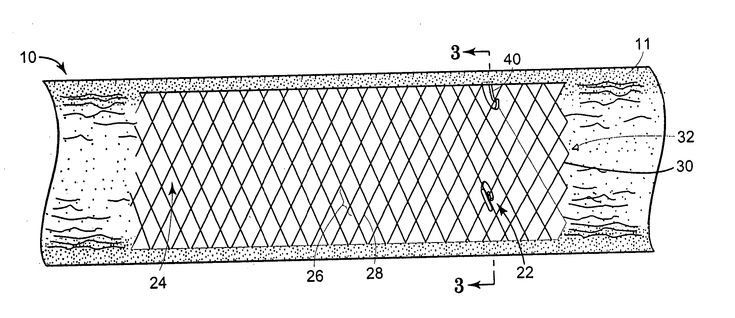
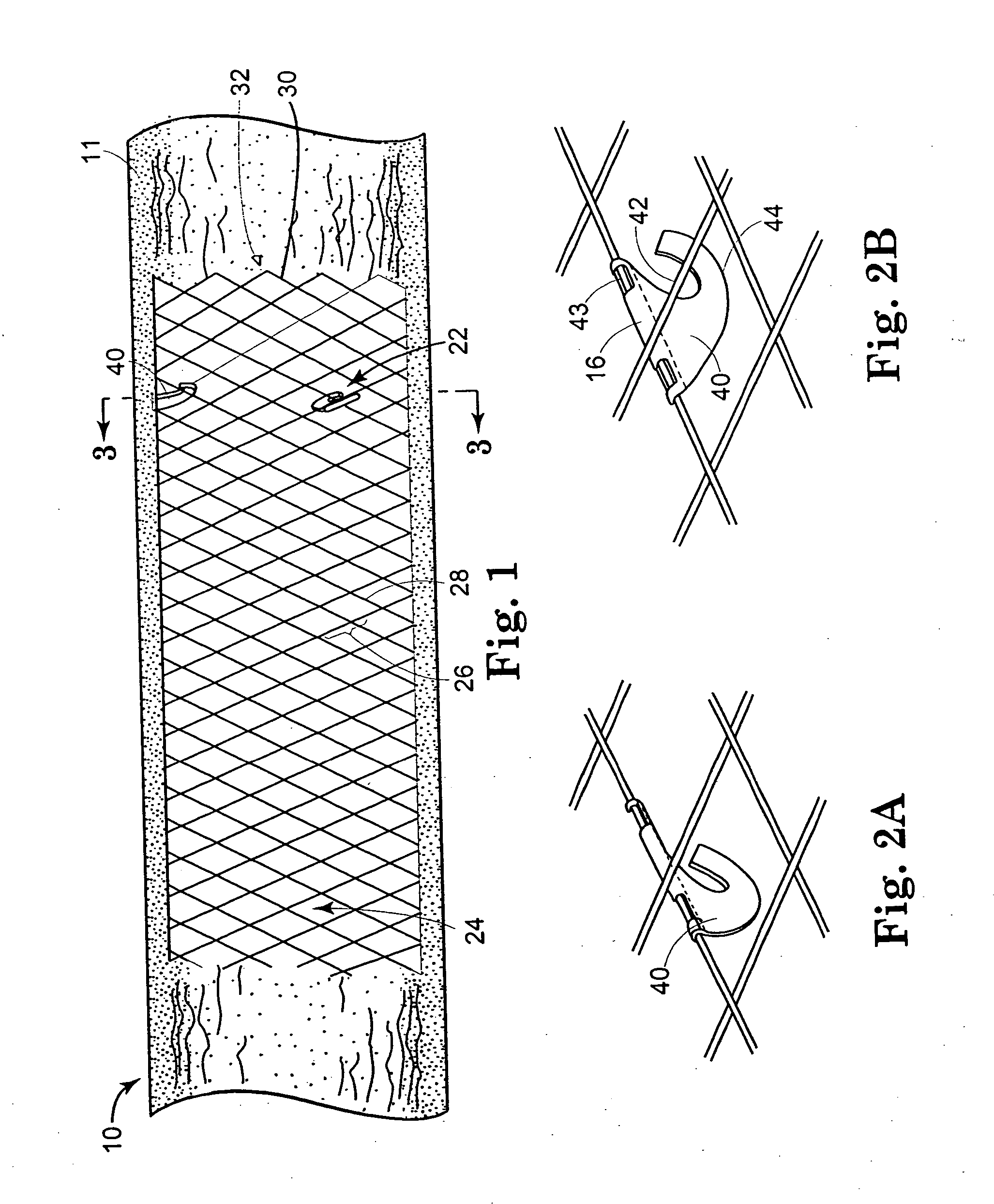
[0038]FIG. 1 shows a representative view of a removable stent 10 in situ within a body vessel 11. For convenience and ease of comprehension, the medical device referenced in the text and figures of the present disclosure is a stent. However, it should be noted that other medical devices or prosthesis including, but not limited to, balloons, stent coverings, vascular grafts, or other implantable devices, are also within the scope of the claimed invention.

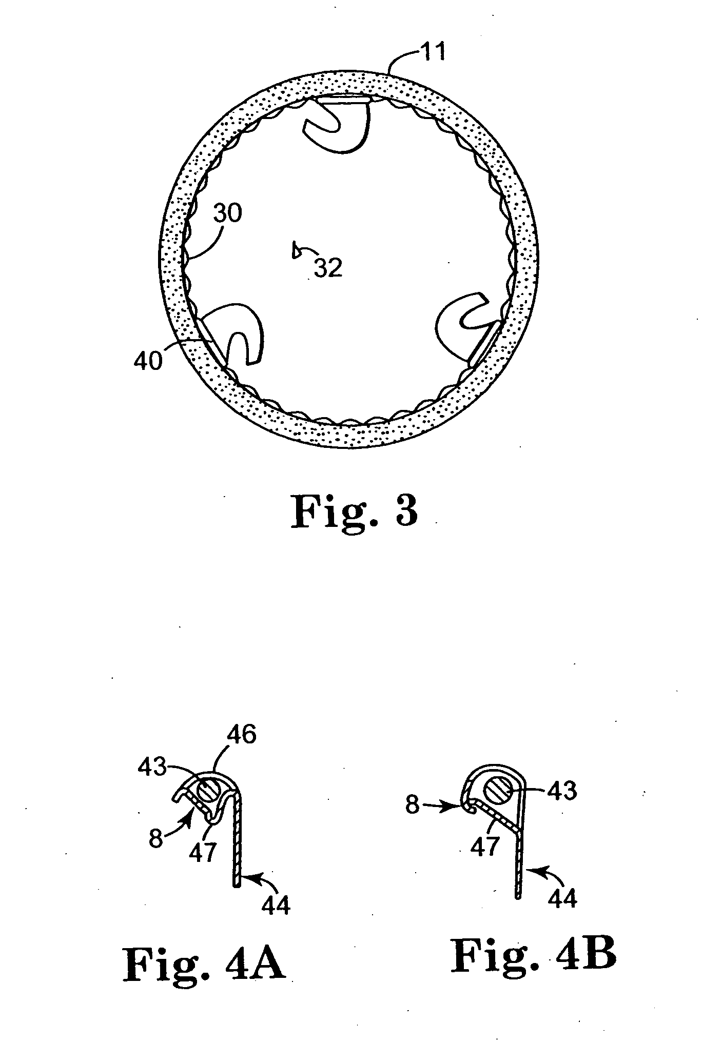
[0039] The removable stent 10 is an intraluminal prosthesis or device having proximal 22 and distal ends 24 that are open. The removable stent is generally tubular in shape and has an outer surface 30 which contains an inner lumen 32 that extends axially between collapsible proximal 22 and distal ends 24. A removable stent includes collapsing elements 40, which aid in collapsing or compressing the stent 10 for its removal from an intralumenal site. The collapsing element 40 of the stent is a feature that aids in its efficient and ea...


PUM


Abstract

A removable stent system and method for extraction of a removable stent from a target site is disclosed. The removable stent includes a removable stent having a collapsible end and a collapsing element configured for coupling with a removal tool. The collapsing element can be configured as a lasso or can be movable between two positions when deployed at a target site in vivo. The removable stent overcomes disadvantages and limitations of previous types of stents as well as overcoming complications during or following stent deployment in vivo. The removable stent further includes features that increase its ease of use and reduce the maneuvering required of devices or tools used to remove the stent. This then decreases the amount of effort required by the physician, the procedure time, and the level of discomfort experienced by a patient during the procedure.

Description

FIELD OF THE INVENTION [0001] The present invention relates generally to a removable stent and an assembly for its delivery or removal from a target site. The present invention particularly relates to a removable stent and system for its use in a medical procedure involving blood vessels, ducts, treatment of enlarged prostate gland, coronary artery disease and the like. BACKGROUND OF THE INVENTION [0002] Stents are used in a wide variety of medical procedures where the permanent expansion of an occluded vessel is desired. Usually, stents are constructed of a metal cylinder that is implanted into a patient at the site of obstruction. In a patient suffering from an occluded vessel, balloon catheterization or balloon angioplasty is often the prescribed treatment. However, following such a procedure, restenosis or re-narrowing of the occluded tissue often occurs. Therefore, stents were developed and are used to optimize and improve the initial and long-term outcome in patients treated f...

Claims


Application Information

Patent Timeline
Patent Type & Authority Applications(United States)
IPC IPC(8): A61F2/90
CPCA61F2/848A61F2/90A61F2002/9528A61F2002/9511A61F2/95
Inventor BOLEA, STEPHEN L.RYKHUS, ROBERT L. JR.HAUSCHILD, SIDNEY F.NEISZ, JOHANN J.POLYAK, MARKSTAEHLE, BRADFORD G.
Owner BOLEA STEPHEN L
Why Eureka
Try Eureka