Flade gas turbine engine with fixed geometry inlet

Active Publication Date: 2005-04-21
GENERAL ELECTRIC CO
View PDF33 Cites 85 Cited by
  • Summary
  • Abstract
  • Description
  • Claims
  • Application Information

AI Technical Summary

Benefits of technology

[0010] One embodiment of the propulsion system is designed for a supersonic aircraft in which the fixed geometry inlet duct extends between an air intake mounted flush with respect to the aircraft's fuselage and the engine inlet. The FLADE engine is mounted within the fuselage. The aircraft and propulsion system with the FLADE engine and fixed geometry inlet duct a

Problems solved by technology

As the aircraft reaches transonic speeds, the airflow demands of the engine may also supersede the efficient supplying ability of the inlet duct because the inlet duct throat becomes choked.
The disadvantages of variable inlet ducts and aircraft incorporating them is their complexity and their s

Method used


Image

  • Flade gas turbine engine with fixed geometry inlet
  • Flade gas turbine engine with fixed geometry inlet
  • Flade gas turbine engine with fixed geometry inlet

Examples


Embodiment Construction

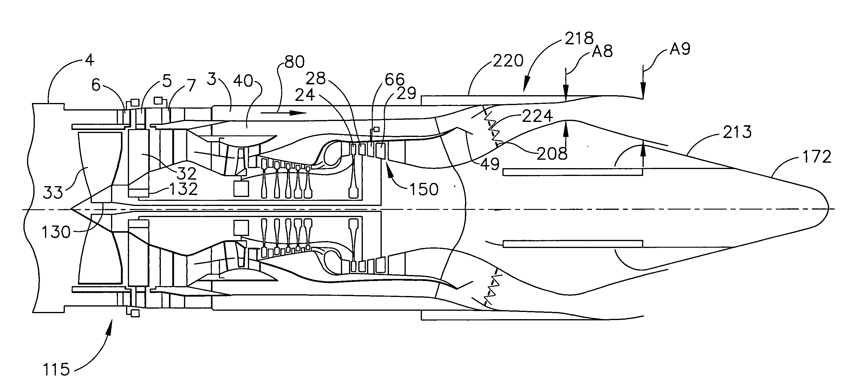
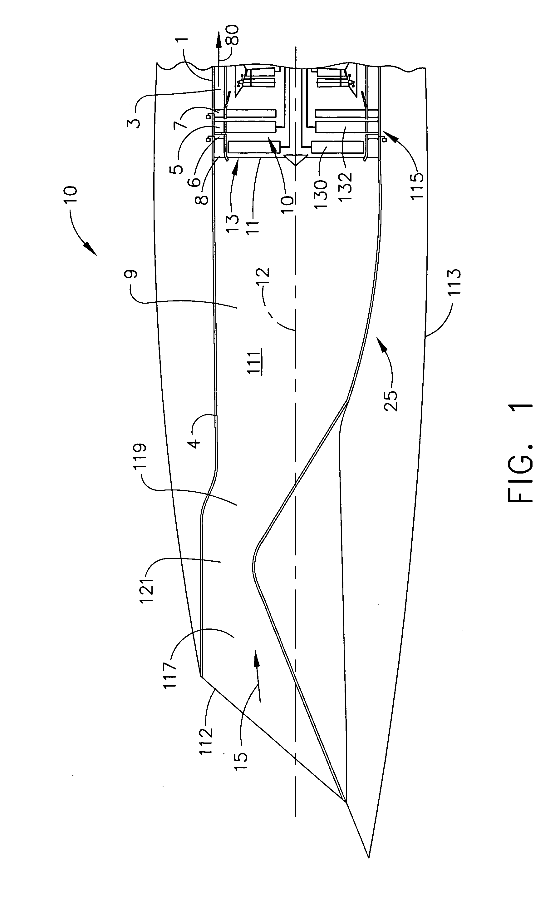
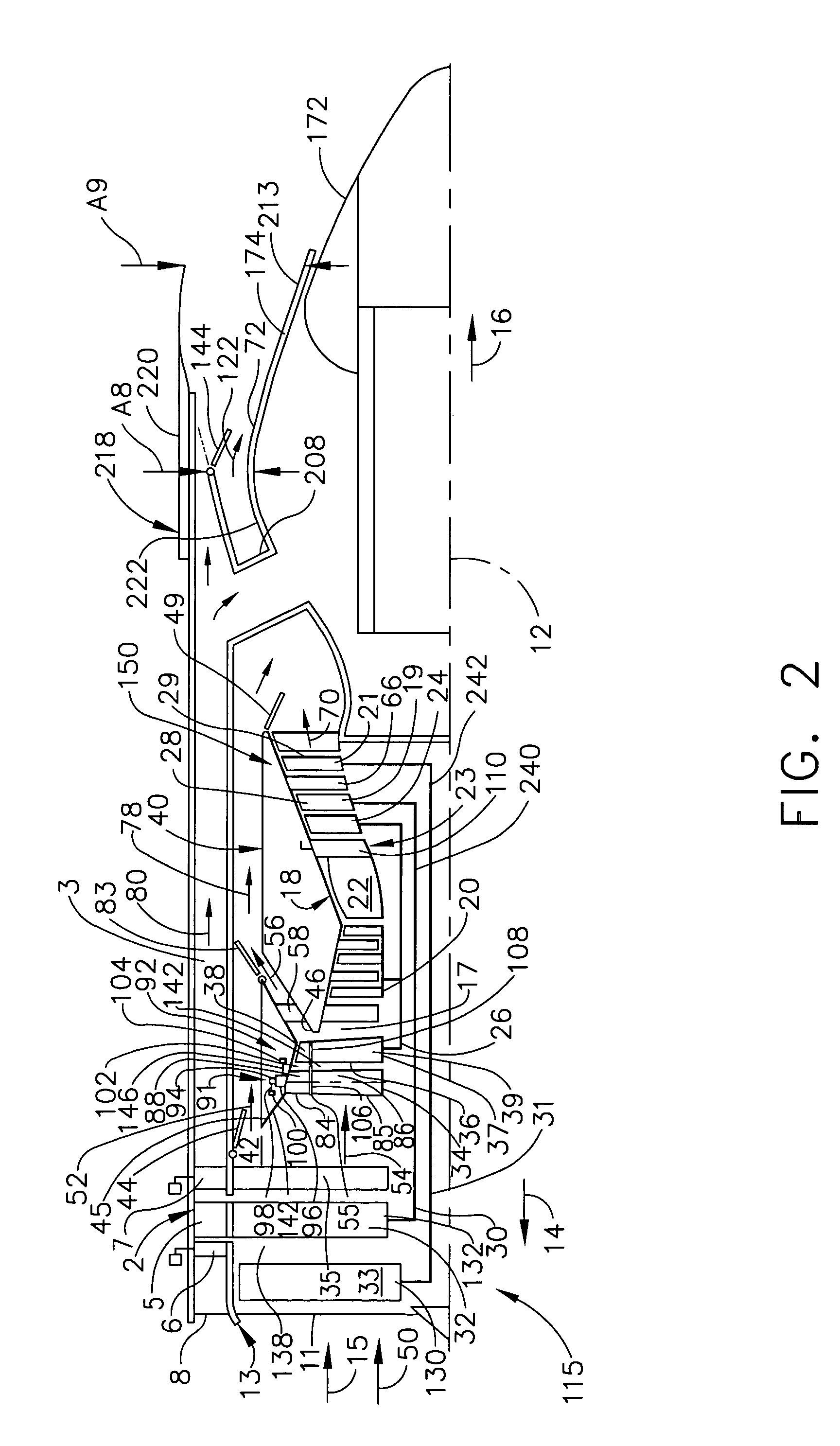
[0018] Schematically illustrated in cross-section in FIG. 1 is a supersonic aircraft 10 having a propulsion system 25 that includes a fixed geometry inlet duct 4 leading to an aircraft FLADE engine 1 which is mounted within the aircraft's main body or fuselage 113. The embodiment of the propulsion system illustrated herein further includes a flush mounted supersonic air intake 112 to the fixed geometry inlet duct 4. The air intake 112 is mounted flush with respect to the aircraft's main body or fuselage 113. The fixed geometry inlet duct 4 extends between the air intake 112 and the engine inlet 13. The fixed geometry inlet duct 4 includes a convergent / divergent inlet duct passage 111 for supplying all of the airflow requirements of the aircraft's FLADE engine 1. The convergent / divergent inlet duct passage 111 is illustrated as, but not limited to, a convergent / divergent two-dimensional type having convergent and divergent sections 117 and 119 and a throat 121 therebetween. The fixed...


PUM


Abstract

An aircraft propulsion system includes a gas turbine engine having a fan section, at least one row of FLADE fan blades disposed radially outwardly of and drivingly connected to the fan section, the row of FLADE fan blades radially extending across a FLADE duct circumscribing the fan section, an engine inlet including a fan inlet to the fan section and an annular FLADE inlet to the FLADE duct. A fixed geometry inlet duct is in direct flow communication with the engine inlet. The fan section may include only a single direction of rotation fan or alternatively axially spaced apart first and second counter-rotatable fans in which the FLADE fan blades are drivingly connected to one of the first and second counter-rotatable fans. The row of FLADE fan blades may be disposed between rows of variable first and second FLADE vanes.

Description

BACKGROUND OF THE INVENTION [0001] 1. Field of the Invention [0002] This invention relates to FLADE aircraft gas turbine engines and, more particularly, to such engines with fixed geometry inlet ducts. [0003] 2. Description of Related Art [0004] High speed aircraft such as those designed to operate in the Mach 2-2.5 range typically require variable geometry inlet ducts to supply air to gas turbine engines that power the aircraft. Jet aircraft engines which are designed to operate at speeds ranging from take-off, through subsonic and transonic, and into the supersonic, require complex air inlet configurations in order to operate efficiently throughout the entire operating range. At lower subsonic speeds, particularly at take-off, it is desirable to allow the engine maximum access to air, since at these lower speeds there is no substantial “ramming” effect produced, whereby air is literally forced into the engine. [0005] The amount of air that can be used by the engine is limited by t...

Claims


Application Information

Patent Timeline
IPC IPC(8): B64D33/02F02C7/04F02C7/18F02K1/12F02K3/06F02K3/11
CPCB64D2033/026B64D33/02
Inventor JOHNSON, JAMES EDWARD
Owner GENERAL ELECTRIC CO
Why Eureka
Try Eureka