Travel control method for travel vehicle

a technology for controlling methods and travel vehicles, applied in locomotives, locomotive transmissions, train hauling devices, etc., can solve problems such as wear and tear and the wear of rails and wheels becomes more conspicuous

Active Publication Date: 2005-04-21
DAIFUKU CO LTD
View PDF4 Cites 11 Cited by
  • Summary
  • Abstract
  • Description
  • Claims
  • Application Information

AI Technical Summary

Benefits of technology

[0007] It is an object of the present invention to provide a travel control method for a travel vehicle, by which the travel vehicle can pass through a curve portion of a travel path at a high speed.

Problems solved by technology

In such a conventional travel control method for a travel vehicle as described above, the conveying cart with travel driving units attached to the respective wheels at the front and rear has posed a problem that when a cart speed is attempted to be maintained at a prescribed value, the wheels are caused to differ from one another in the number or rotations, therefore if the wheels are driven to rotate at a same speed, the rails and the wheels are caused to wear by the spinning of the wheels.
Further, if the travel cart passes through a curve at a high speed, the wear of the rails and wheels becomes more conspicuous.

Method used


Image

  • Travel control method for travel vehicle
  • Travel control method for travel vehicle
  • Travel control method for travel vehicle

Examples


Embodiment Construction

[0023] Description will be given of embodiments of the present invention below, based on the accompanying drawings.

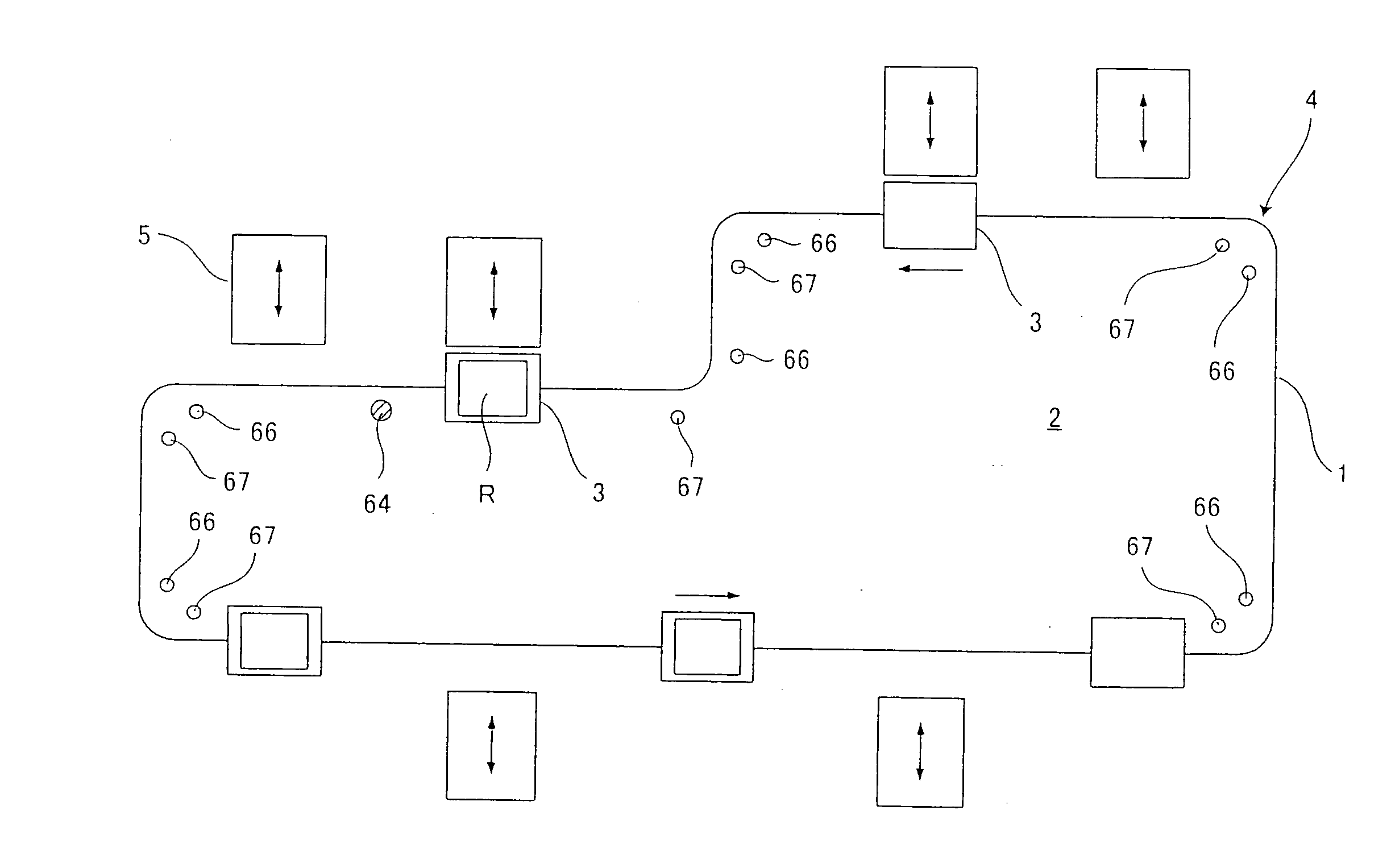
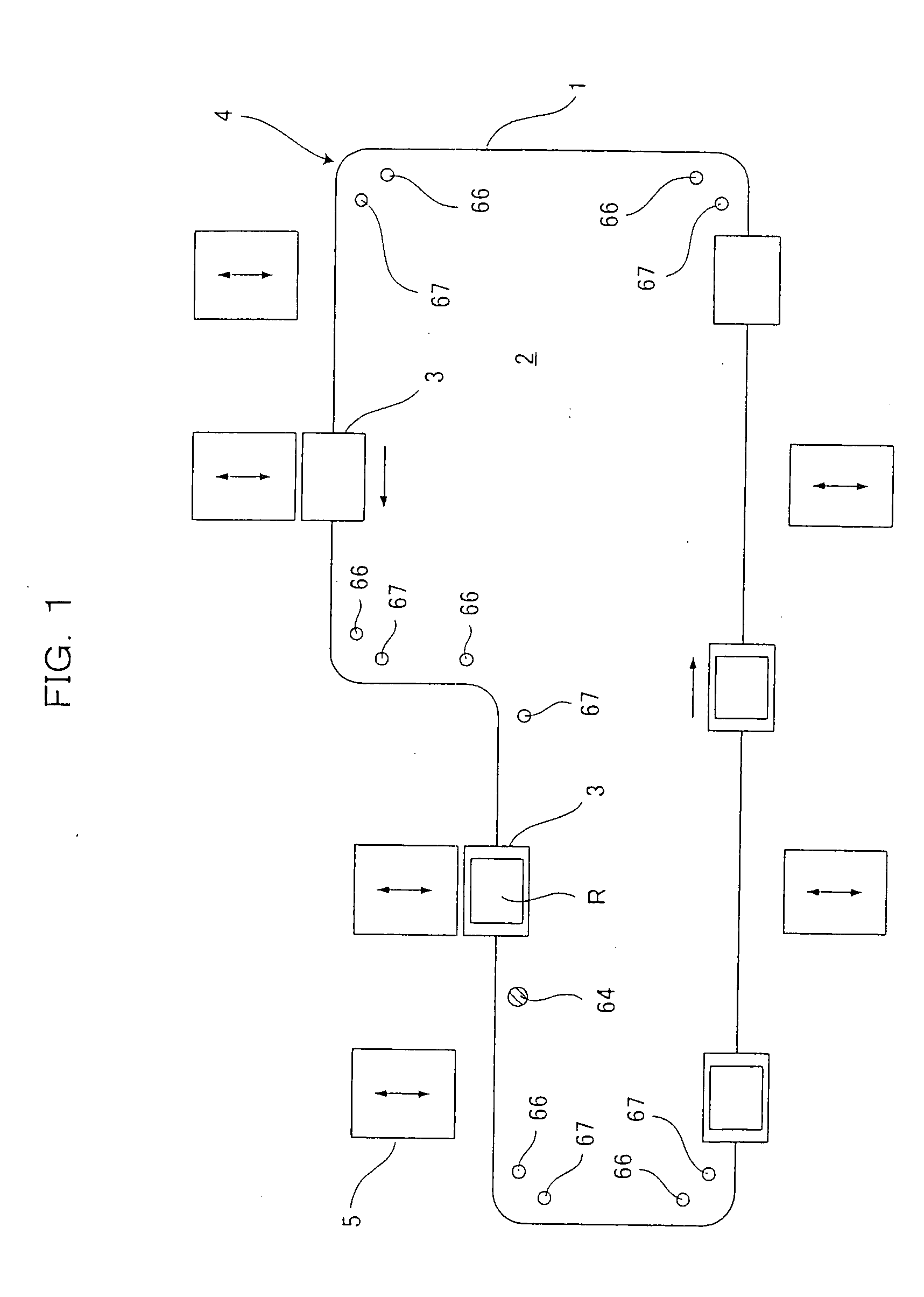
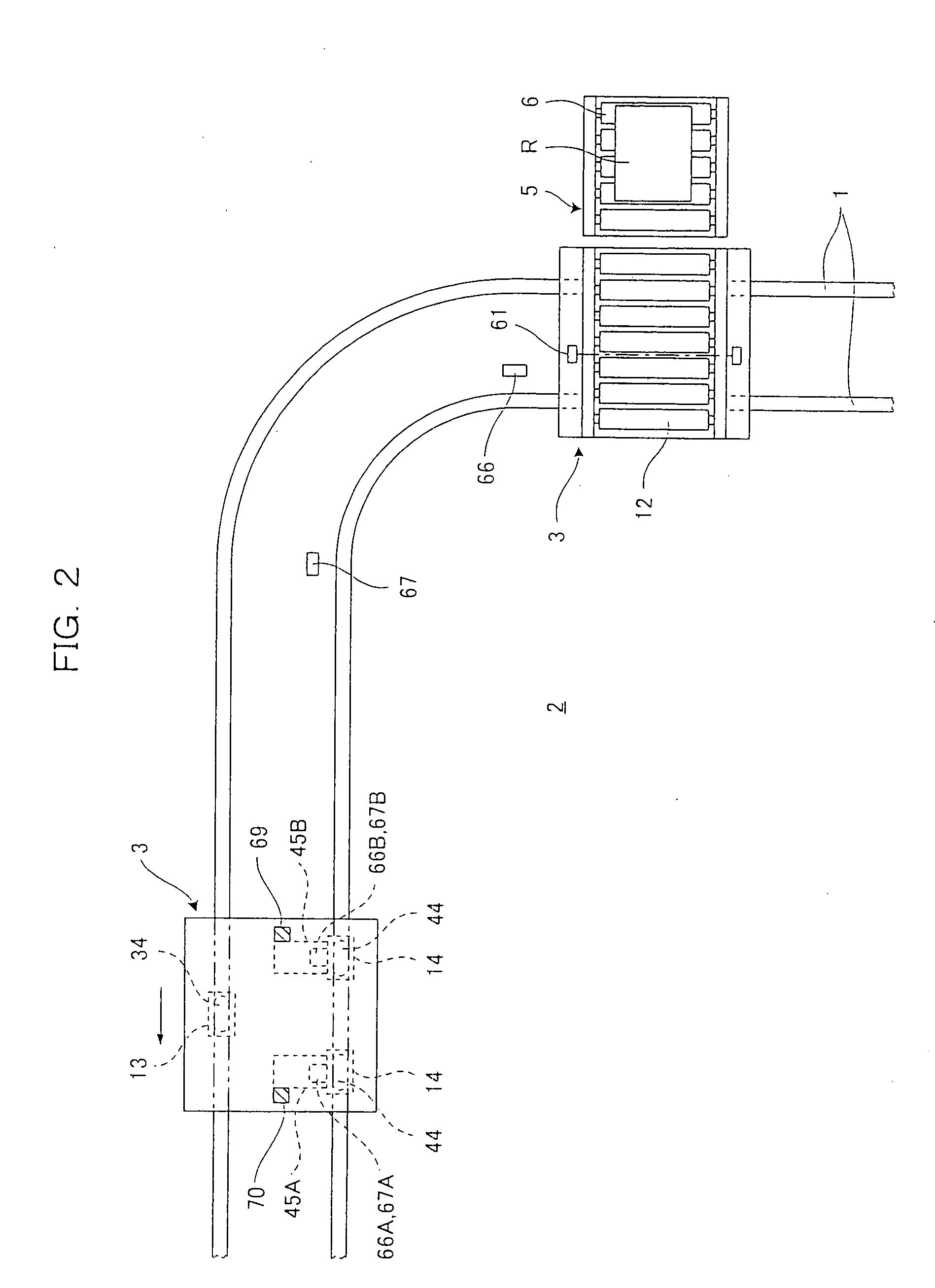
[0024] Description will be given of a travel control method for a travel vehicle of the present invention, taking up a case where the method is applied to a conveying cart included in an article conveying system. FIG. 1 is a travel path diagram of an article conveying system in an embodiment of the present invention and FIG. 2 is a diagram of a structure of a main part of the article conveying system.

[0025] In FIGS. 1 and 2, a numerical symbol 1 indicates a pair of rails laid out on a floor 2, and 3 tree-wheel conveying carts (an example of the travel vehicle) traveling while being guided by the travel rails 1 to convey an article R. Note that the total number of three-wheel conveying carts is five.

[0026] A travel path 4, which is a loop having linear portions, clockwise curve portions and a counterclockwise curve portion, is constituted of the travel rails 1 and plu...


PUM


Abstract

In a conveying cart, a front side wheel (a front wheel) for supporting the conveying cart is provided with a travel driving unit (a front wheel inverter and a travel motor), and a rear side wheel (a rear wheel) for supporting the conveying cart is provided with a travel driving unit (a rear wheel inverter and a travel motor). When the conveying cart travels in a curve portion of a travel path, the travel driving unit for the front wheel of the conveying cart on which the center of gravity is located is subjected to speed control, and the travel driving unit for the rear wheel of the conveying cart that tends to float up is subjected to torque control.

Description

BACKGROUND OF THE INVENTION [0001] 1. Field of the Invention [0002] The present invention relates to a travel control method for a travel vehicle which is supported by wheels provided at the front and rear thereof and which travels while being guided by a travel path. [0003] 2. Description of the Related Art [0004] As a conventional travel control method for a travel vehicle of this kind, a travel control method for a travel vehicle as described below has been disclosed. [0005] The travel vehicle is a conveying cart which travels while being guided by guide rails in a loop, for example, and conveys an article between stations disposed along the guide rails. Wheels mounted at the front and rear of the conveying cart are provided with travel driving units, respectively. A conveying cart travels to a target station by driving the travel driving units according to an article conveyance command, thereby to convey the article. [0006] In such a conventional travel control method for a trav...

Claims


Application Information

Patent Timeline
Patent Type & Authority Applications(United States)
IPC IPC(8): B60L15/20B61B13/00B61K1/00G05D1/02
CPCY02T10/7258B66F9/072Y02T10/72
Inventor KOIDE, HIROYUKI
Owner DAIFUKU CO LTD
Why Eureka
Try Eureka