Heddle shaft with novel corner connector

a corner connector and heddle shaft technology, applied in the field of heddle shafts, can solve the problems of severe vibration load on the heddle shaft, and achieve the effect of low production cost and quick and simple corner connection

Inactive Publication Date: 2005-04-21
GROZ BECKERT KG
View PDF5 Cites 42 Cited by
  • Summary
  • Abstract
  • Description
  • Claims
  • Application Information

AI Technical Summary

Benefits of technology

[0010] The heddle shaft of the invention has a connecting piece which can be inserted into the hollow chamber, open on its end, of the shaft rod and secured there in detent fashion. In a sense it is clipped into place, requiring neither special skills no

Problems solved by technology

In high-output power looms, the heddle sh

Method used


Image

  • Heddle shaft with novel corner connector
  • Heddle shaft with novel corner connector
  • Heddle shaft with novel corner connector

Examples


Embodiment Construction

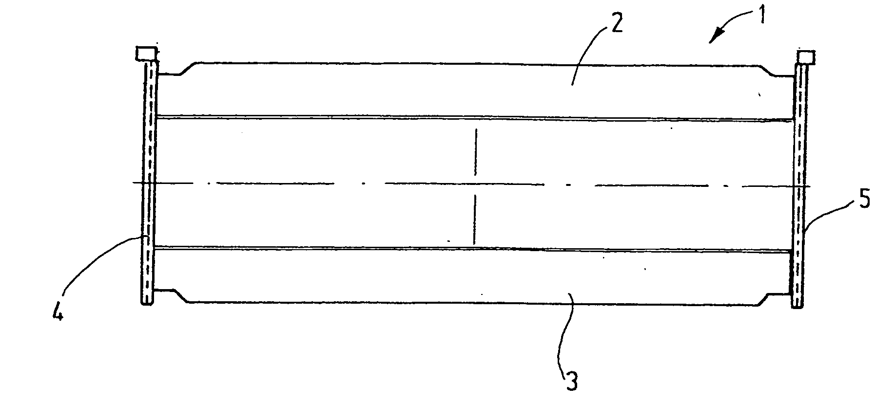
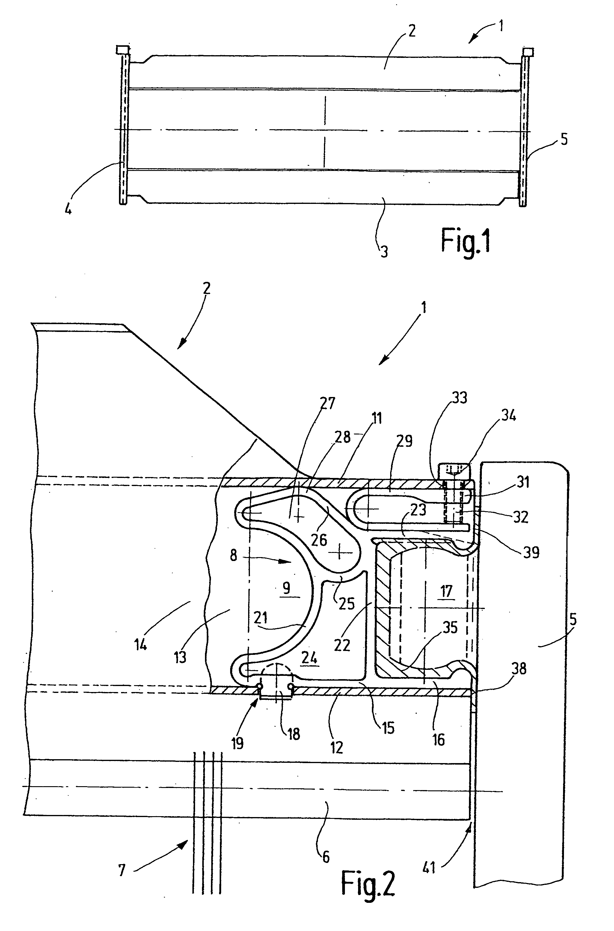
[0035] The heddle shaft 1 seen in FIG. 1 is distinguished in particular by the type of connection between the shaft rods 2, 3 and the lateral bracing posts 4, 5. This connection is shown in FIG. 2 as a representative of all four corner connections.

[0036] An essential element of the corner connection is formed by a connecting piece 8, which may be a plastic injection-molded element. It is inserted into a hollow chamber 9 of the shaft rod 2 that is defined at the top and bottom by a respective strut 11, 12 and by side walls 13, 14 and preferably has an approximately rectangular cross section. The shaft rod 2 may have one or more such hollow chambers. The cross section of the hollow chamber 9 preferably has a width (perpendicular to the plane of the drawing in FIG. 2) that is substantially less than its height. The height is the spacing between the struts 11 and 12. It is shown in FIG. 2 in the vertical direction, parallel to the plane of the drawing.

[0037] The connecting piece 8 is ...


PUM


Abstract

A novel corner connector for heddle shafts has detent means with which it can be retained in a shaft rod. The load-related locking is effected independently of the detent means by a clamping device that acts between the struts of the shaft rod.

Description

CROSS REFERENCE TO RELATED APPLICATION [0001] This application claims the priority of German Patent Application No. 103 49 381.6, filed on Oct. 21, 2003, the subject matter of which, in its entirety, is incorporated herein by reference. FIELD OF THE INVENTION [0002] The invention relates to a heddle shaft for power looms. In power looms, heddle shafts are used for instance for shedding. They have an upper and a lower shaft rod, which are joined together at their ends by lateral bracing posts. The upper and lower shaft rods are provided with heddle support rails, on which the heddles in large numbers are retained parallel to one another. Upon setup of the power loom, for instance because of a product change, heddle shafts must sometimes be removed from the loom. It is also necessary, for instance for changing the heddles, to remove the heddle shafts by removing the lateral bracing posts from the shaft rods. BACKGROUND OF THE INVENTION [0003] In high-output power looms, the heddle sha...

Claims


Application Information

Patent Timeline
IPC IPC(8): D03C9/06
CPCD03C9/0691D03C9/0675
Inventor SCHWANE, HERBERTSTEFFEN, RICHARDOLBING, ANDREGESING, KARL-HEINZ
Owner GROZ BECKERT KG
Why Eureka
Try Eureka