Non-refillable valve

Inactive Publication Date: 2005-04-21
DISCOUNT REFRIGERANTS
View PDF23 Cites 7 Cited by
  • Summary
  • Abstract
  • Description
  • Claims
  • Application Information

AI Technical Summary

Benefits of technology

[0007] One object of the present invention is to provide a nonrefillable valve for pressure containers, for example, cylinders used in industrial applications to hold and store pressurized industrial gas. Another object of the invention is to provide a valve which easily permits discharge of the pressure container, but will automatically prevent refilling of the container without the user or operator of the valve having to further manipulate the valve. Another object of the invention is to provide the above described functionality with a valve of simple and reliable construction.
[0013] The valve core may be one integral unit made of a resilient material, such as natural or synthetic rubber. Alternatively, the valve core may include a valve core body, and a sealing member which includes a resilient sealing surface for engagement with the valve seat. The valve core flange can also be shaped to accommodate the particular constriction formed within the chamber. The valve core flange can be shaped or configured allowing it to be compressed or moved downwardly past the constriction without undue force, yet the valve core flange configuration makes it much more difficult to return the valve core to its first position. For example, the lower end of the valve core flange can be slightly tapered, while the upper end can have a distinct edge or corner preventing it from being easily forced upwardly beyond the constriction.

Problems solved by technology

Thus, such pressure containers can be initially charged or filled with the refrigerant; however, once the refrigerant has been discharged from the container, the container may not be refilled again.

Method used


Image

  • Non-refillable valve
  • Non-refillable valve
  • Non-refillable valve

Examples


Embodiment Construction

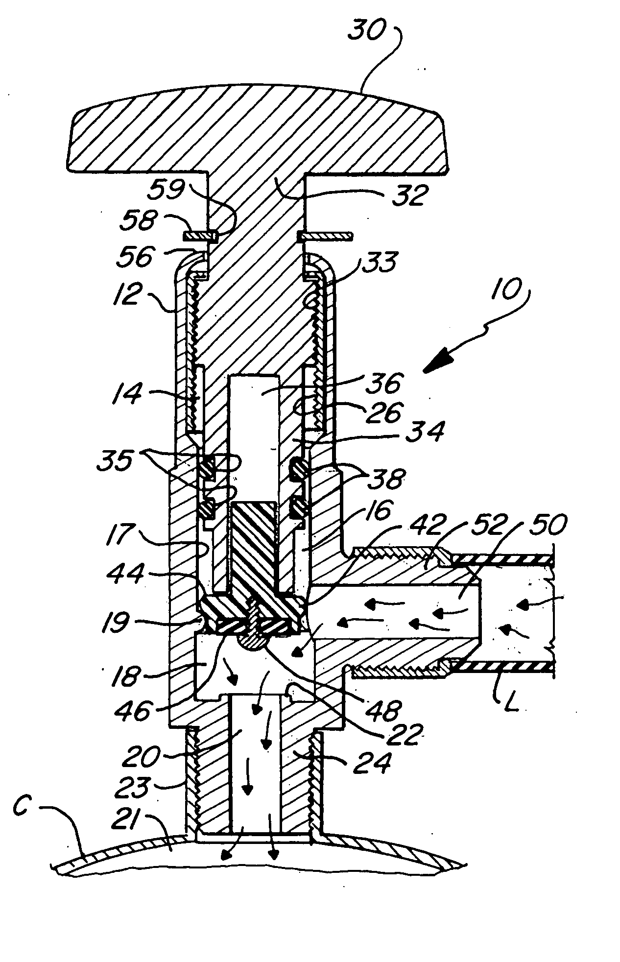
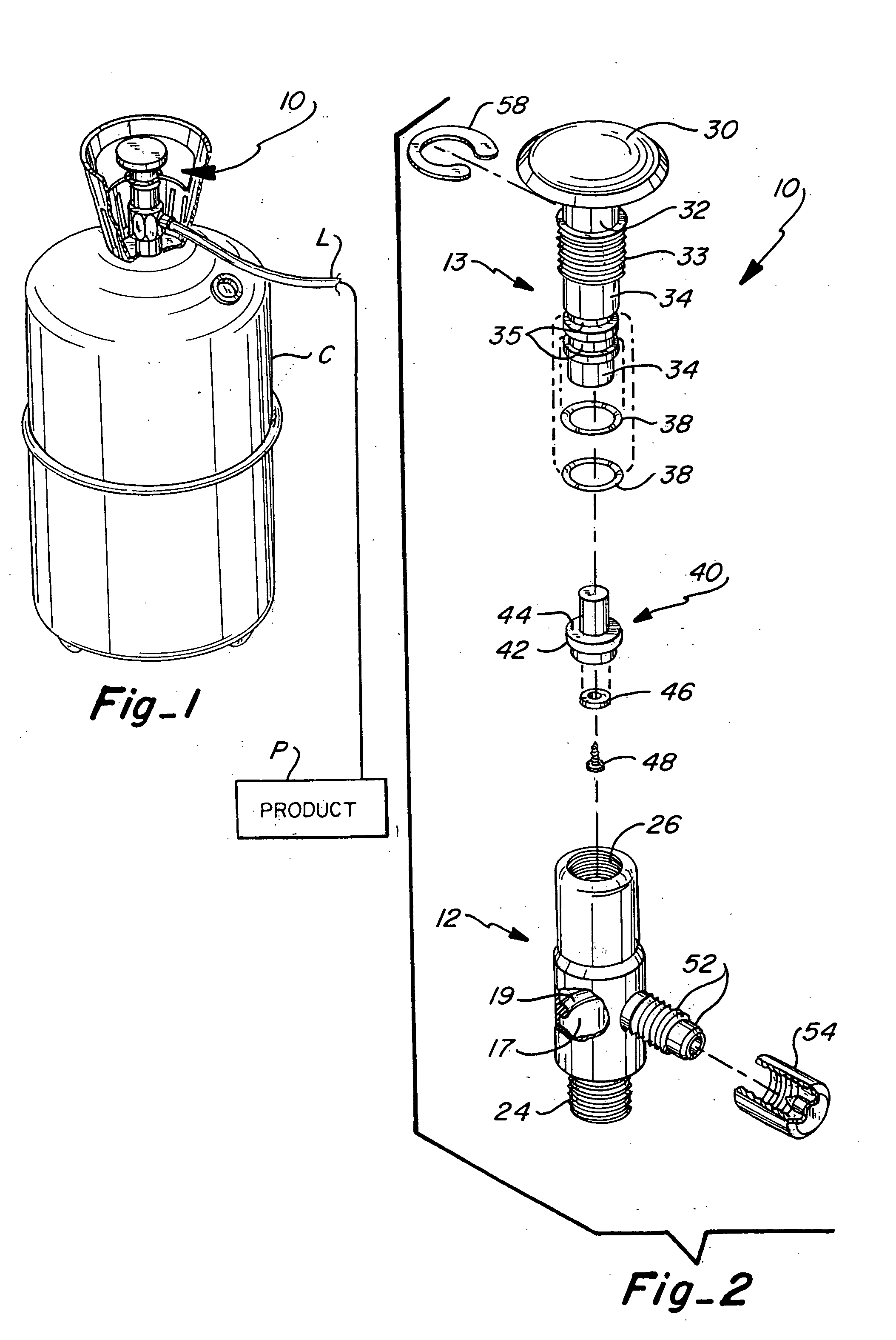
[0021] Referring to FIG. 1, a pressure container or pressure vessel C is provided with the nonrefillable valve 10 of the invention for filling and selective emptying of the container C. Valve 10 can be welded, threaded or otherwise affixed to the container C. In order to fill the container, a product source P produces a flow of fluid through line L which communicates with the valve 10. Container C simply represents a common industrial cylinder or tank which is specifically designed to hold a pressurized fluid / gas therein.

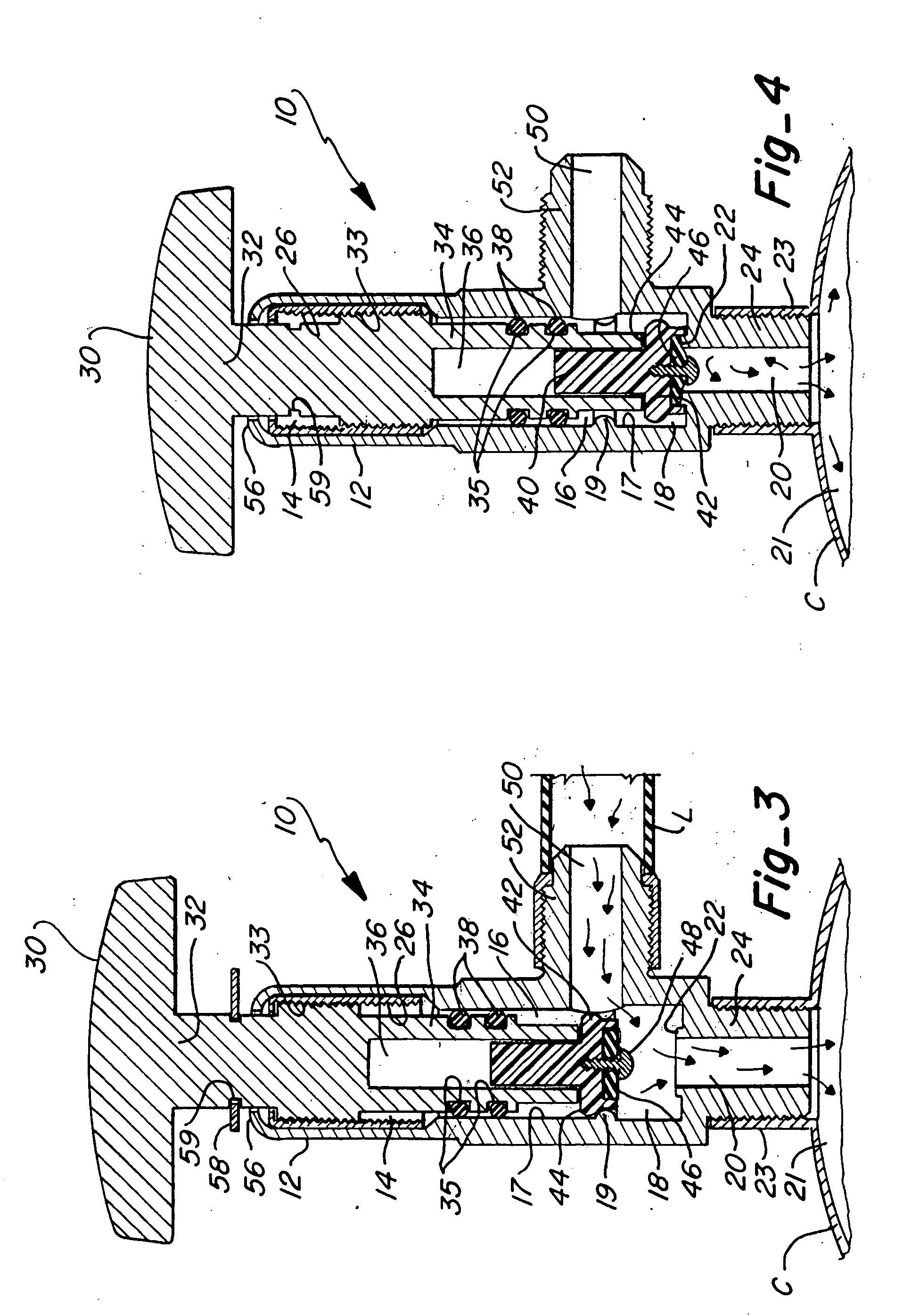
[0022] Now referring to FIGS. 2 and 3, the primary components of the valve 10 include a valve body 12 and a valve operating assembly 13, including a number of working parts which are received in the valve body when assembled. The valve body 12 is a cylindrical shaped member including a chamber extending longitudinally therethrough. When the valve operating assembly 13 is positioned within the chamber, the chamber can be conceptually separated into an upper portion ...


PUM


Abstract

A nonrefillable valve is provided that allows for an initial filling of a container, but prevents subsequent refilling of the container. The valve operating assembly includes a valve stem and a valve core which is slidably received in the distal end of the valve stem. In a first position, the valve core resides above a rim or protrusion within the chamber. After filling of the container, a second position is defined when the valve stem is operated to force the valve core beyond the protrusion and in seating engagement with a valve seat, thus sealing the container. The valve is then selectively operated in a third or open position to discharge the container as desired. Subsequent refilling of the container is prevented by the force of fluid reentering the valve which forces the valve core to its seated engagement with the valve seat.

Description

REFERENCE TO RELATED APPLICATIONS [0001] This is a continuation application of U.S. patent application Ser. No. 09 / 948,328 filed on Sep. 6, 2001, and entitled “Non-refillable Valve”, which is incorporated herein by reference in its entirety.FIELD OF THE INVENTION [0002] This invention relates to nonrefillable or single use valves used in pressurized systems. More particularly, the invention relates to a nonrefillable valve especially adapted for use with pressurized vessels or containers wherein the construction of the valve allows the pressure container to be filled once, and then selectively discharged; however, subsequent refill of the pressure container is prevented. BACKGROUND OF THE INVENTION [0003] Valves are commonly used to control the discharge of fluid from a pressure container or vessel. Typically, such valves include a handle or some other means by which a user can selectively control discharge of the container. Pressure containers may contain any number of products suc...

Claims


Application Information

Patent Timeline
IPC IPC(8): F16K1/30
CPCF16K1/302Y10T137/88054
Inventor CHEN, DE FU
Owner DISCOUNT REFRIGERANTS
Why Eureka
Try Eureka