Inserta clamp

Inactive Publication Date: 2005-04-21
VALTRA
View PDF3 Cites 19 Cited by
  • Summary
  • Abstract
  • Description
  • Claims
  • Application Information

AI Technical Summary

Benefits of technology

[0008] It is the intention of the present invention to provide a clamping device to hold a workpiece tightly, quickly and conveniently anywhere on the working surface of a table, a workbench, or a machine tool regardless of the size of the workpiece and the working surface. Another intention is to enable the present invention to clamp workpiece anywhere on the working surface without the use of clamping bars, beams or fixtures. Yet another intention of the present invention is to enable the clamping of a workpiece against the working surface without crossing over the edge and reaching the bottom of the work table, workbench or machine tool. It is als

Problems solved by technology

However, when the workpiece and the workbench are relatively large, the middle part of the workpiece will be out of the reach of the clamping arms and clamping pads.
This is a logical way to solve the problem, but it is also a very time consuming and i

Method used


Image

  • Inserta clamp
  • Inserta clamp
  • Inserta clamp

Examples


Embodiment Construction

[0017] With the help of the drawings and the detail description below, the features of the present invention will be apparent and fully understandable.

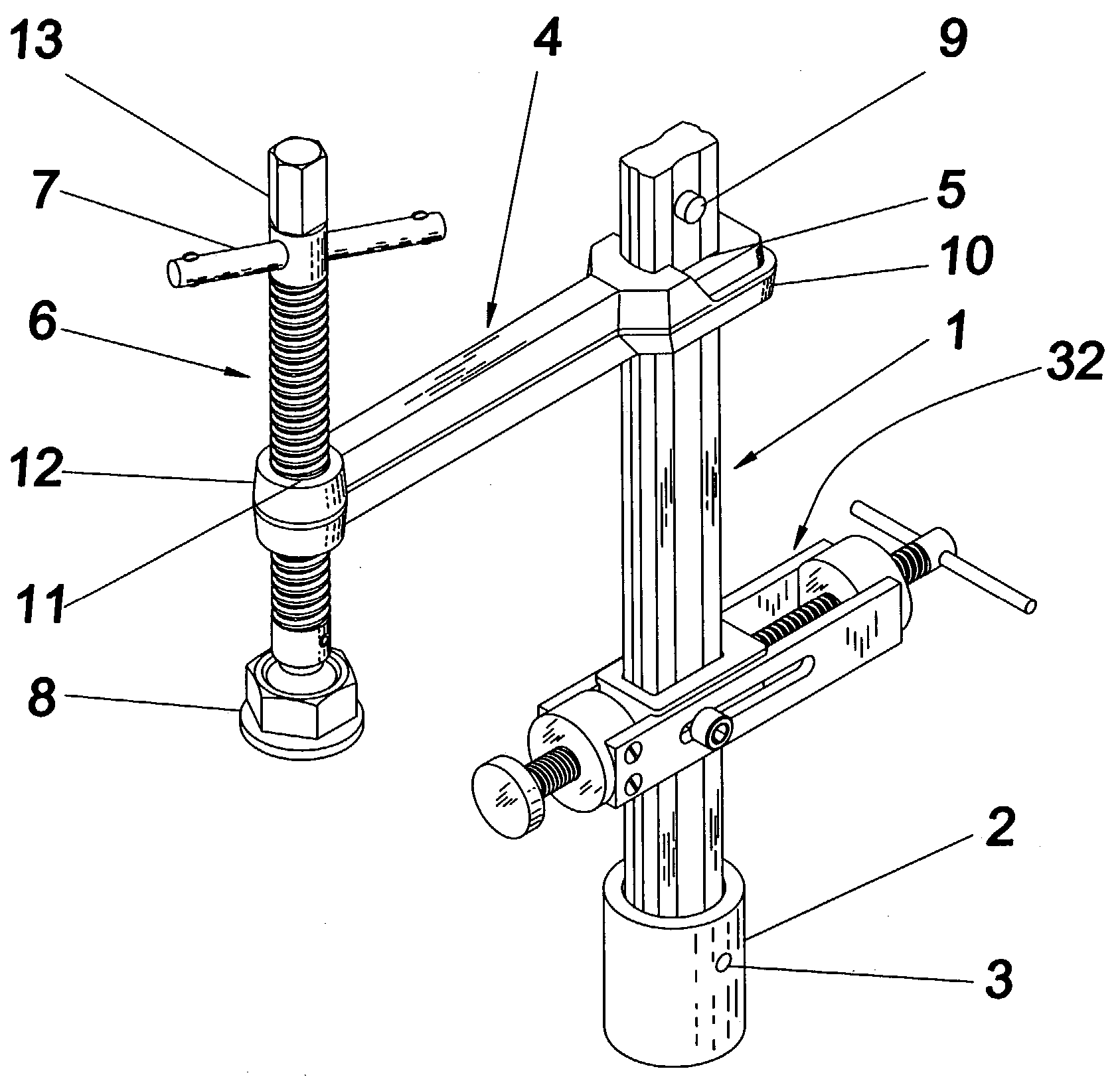
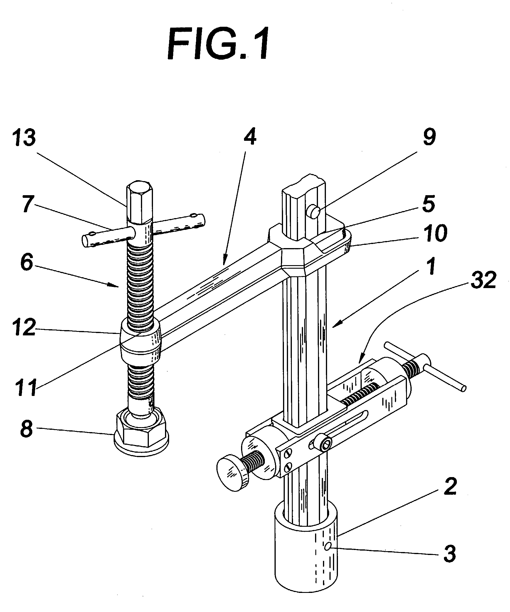
[0018] Referring to FIG. 1, the present invention, inserta clamp comprises a straight shank 1, a short cylindrical sleeve 2 attached and fixed to the lower end of shank 1 by taper pin 3, and a movable arm 4 with one end slid over the top end of shank 1 through rectangular hole 5 and the other end fitted with a threaded rod 6, turning handle 7 and the clamping pad 8. The straight shank 1 acts as the fixed arm of a conventional clamp. At the upper end of shank 1, a spring loaded quick release button 9 is equipped to prevent the falling off of the movable arm 4 and other attachments from shank 1, but at the same time it allows quick and easy insertion of these items onto shank 1. Movable arm 4 is a metal bar with a rectangular hole 5 at one end 10 and a cylindrical threaded hole 11 at the other end 12. The upper end of shank 1 is insert...


PUM

PropertyMeasurementUnit
Diameteraaaaaaaaaa
Sizeaaaaaaaaaa

Abstract

The present invention relates to a general purpose clamping device which is called the inserta clamp. It comprises a straight shank with the lower end attached to a short cylindrical sleeve and a movable arm sliding over the shank. Feeding through the free end of the movable arm is a threaded rod with clamping pad and turning handle at the lower end and upper end respectively. The present invention is designed to hold a workpiece tightly, quickly and conveniently on the working surface of a table, workbench or machine tool. And the invention can be relocated easily over the workbench made of wood or metal, or over the working surface of a machine tool. Attachments are provided to enhance the functionality of the invention.

Description

REFERENCE [0001]U.S. PATENT DOCUMENTS2,764,195Sep. 25, 1956William Heimes2,877,815Mar. 17, 1959William A. Fonken3,623,718Nov. 30, 1971Eugene J. Thomeczek, Sr.BACKGROUND OF THE INVENTION [0002] 1. Field of the Invention [0003] The present invention relates to a general purpose clamping device and more particularly to an inserta clamp. The invention is designed to hold a workpiece tightly, quickly and conveniently on the working surface of a table, a workbench, or a machine tool. Yet the invention can be relocated easily for different configuration and can be removed without trouble after work. The working surface of the table or workbench can be made of wood or metal, whereas the working surface of a machine tool is a metal surface with or without tooling holes. [0004] The present invention comprises a straight shank with the lower end attached to a short cylindrical sleeve and a movable arm sliding over the shank. Feeding through the free end of the movable arm is a threaded rod wit...

Claims


Application Information

Patent Timeline
IPC IPC(8): B23Q3/06
CPCY10T29/53909B23Q3/069
Inventor WONG, HARRY
Owner VALTRA
Why Eureka
Try Eureka