Optometric apparatus, optometric method, and optometric server

a technology of optometry and optometry server, which is applied in the field of optometry apparatus, optometric method, and optometric server, can solve the problems of preventing the subject from easily making a proper determination, erroneous vision test, and inability to conduct objective eye examination, so as to achieve accurate measurement of the subject's visual acuity and easy selection of targets.

Inactive Publication Date: 2005-04-21
VISION MEGANEKK
View PDF8 Cites 34 Cited by
  • Summary
  • Abstract
  • Description
  • Claims
  • Application Information

AI Technical Summary

Benefits of technology

[0054] This permits sequential displaying on the screen display unit of a plurality of vision test charts of a combination of targets having a size level difference of two or more. Thus, the subject is allowed only to select the smallest recognizable target on each vision measurement table of a combination of targets having

Problems solved by technology

As a matter of fact, when the consumers measure their visual acuity at home, they cannot conduct the objective eye examination because they have no test apparatus such as the auto-refractometer at home.
This configuration prevents the subject from easily making a proper determination of which target was the smallest one that could be visually clearly identified by the subject.
Consequently, the subject sometimes indicated a preference for a target other than the smallest one that could be visually recognized by the subject, which results in

Method used


Image

  • Optometric apparatus, optometric method, and optometric server
  • Optometric apparatus, optometric method, and optometric server
  • Optometric apparatus, optometric method, and optometric server

Examples


Embodiment Construction

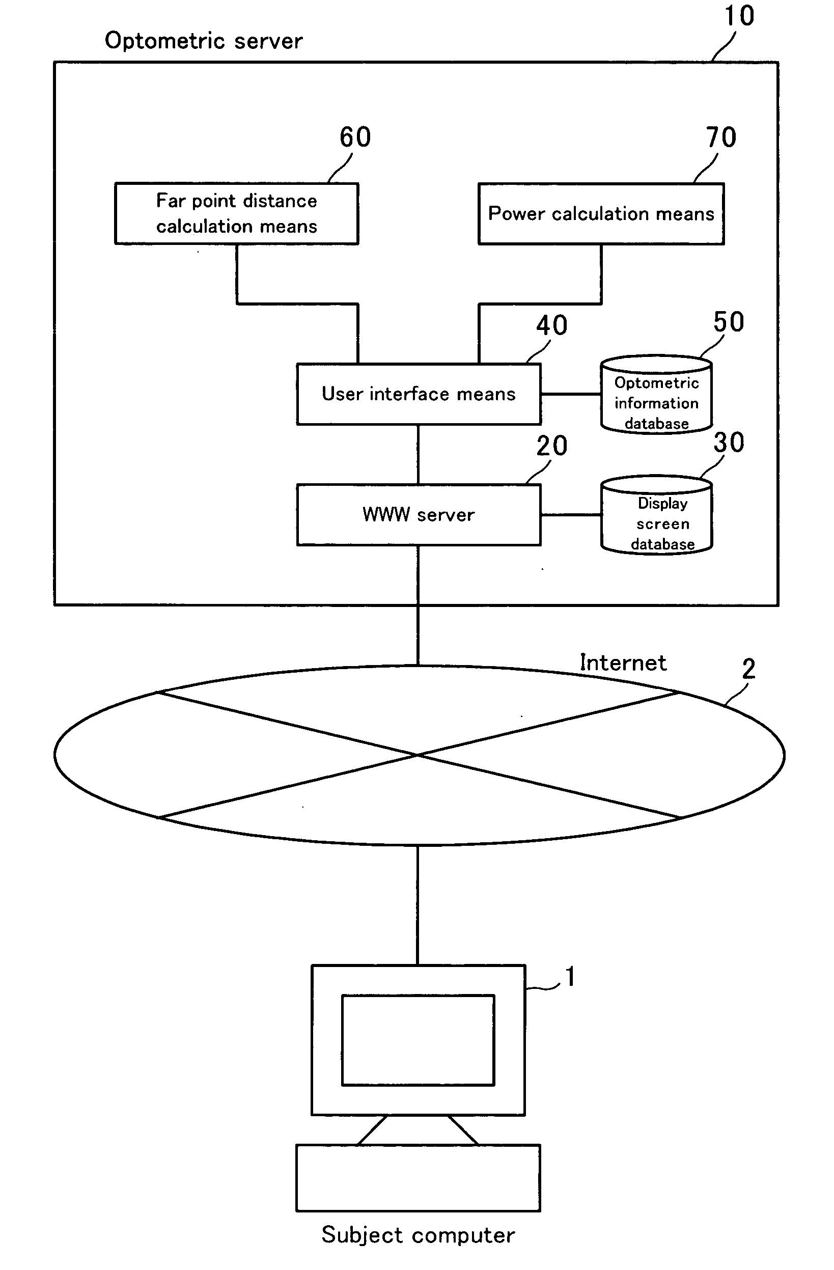
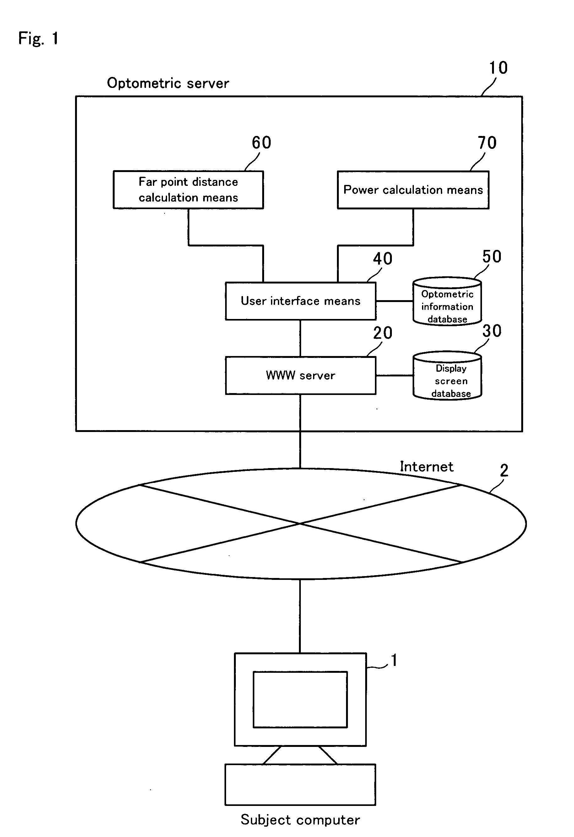
[0076]FIG. 1 shows the system configuration of an optometric apparatus according to a preferred embodiment of the present invention.

[0077] As illustrated, in this system, a computer 1 used by a subject is connected via the Internet 2 to an optometric server 10 for providing an optometric method according to preferred embodiments of the present invention.

[0078] The optometric server 10, which provides an optometric service to the subject computer 1 via the Internet 2, includes a WWW server 20, a display screen database 30, a user interface unit 40, an optometric information database 50, a far point distance calculation unit 60, and a power calculation unit 70.

[0079] When accessed by the subject computer 1, the WWW server 20 provides an optometric function according to an optometric procedure of the present invention. In this preferred embodiment, an HTTP server is used such that the subject computer 1 is served using a general Web browser.

[0080] In accordance with the optometric ...


PUM


Abstract

An optometric apparatus and an optometric method includes the steps of acquiring subject's attributes and an orientation selected by the subject on an astigmatic axis determination chart displayed on the computer screen, displaying vision measurement charts in the acquired orientation and the orientation perpendicular thereto to acquire visual recognition limits selected by the subject, calculating far point distances based on the acquired visual recognition limits and the acquired subject's attributes, and calculating a refractive power based on the acquired orientation and the calculated two far point distances. The far point distance is calculated using a neural network that has been determined by a number of subjects in advance. The astigmatic axis determination chart has four groups of a plurality of parallel lines, each group having lines arranged in their respective orientation, and the vision measurement chart has a plurality of light and dark line images of different sizes, thereby reducing the risk of presenting an erroneous refractive power.

Description

BACKGROUND OF THE INVENTION [0001] 1. Field of the Invention [0002] The present invention relates to an optometric apparatus, an optometric method, and an optometric server for performing eye examinations to determine the refractive power of eyeglasses or contact lenses. More particularly, the invention relates to an optometric apparatus, an optometric method, and an optometric server for performing subjective eye examinations using a computer screen. [0003] 2. Description of the Related Art [0004] Conventionally, a subject must go to an ophthalmologist or to an eyeglass shop to have their visual acuity examined subjectively or objectively by following examiner's instructions. Generally, to perform an objective eye examination, the examiner measures objectively the refractive coefficient of a subject's eye using an auto-refractometer and then lets the subject wear a ready-made corrective lens to check the resulting subject's visual acuity. On the other hand, to perform a subjective ...

Claims


Application Information

Patent Timeline
IPC IPC(8): A61B3/028A61B3/032A61B3/036
CPCA61B3/0033A61B3/0041G06F19/345A61B3/032A61B3/036A61B3/028G16H50/20
Inventor TOSHIMA, AKIOYOSHIDA, TAKEHIKO
Owner VISION MEGANEKK
Why Eureka
Try Eureka