Method and apparatus for scheduling uplink packet transmission in a mobile communication system

a mobile communication system and packet transmission technology, applied in the field of mobile communication systems, can solve the problems of degrading the reception performance of the node b, affecting the reception performance of other uplink signals, and affecting the efficiency of the network, so as to reduce the overhead of uplink signals

Inactive Publication Date: 2005-04-21
SAMSUNG ELECTRONICS CO LTD
View PDF5 Cites 180 Cited by
  • Summary
  • Abstract
  • Description
  • Claims
  • Application Information

AI Technical Summary

Benefits of technology

[0017] The present invention has been designed to substantially solve at least the above problems and / or disadvantages and to provide at least the advantages below. Accordingly, an object of the present invention is to provide a method and apparatus for reducing uplink signaling overhead during uplink packet transmission.
[0018] Another object of the present invention is to provide a method and apparatus for controlling the transmission intervals of buffer status information and CSI on the uplink to reduce signaling overhead.
[0019] A further object of the present invention is to provide a method and apparatus for efficiently transmitting uplink packets by controlling the transmission intervals of buffer status information and CSI.
[0020] Still another object of the present invention is to provide a method and apparatus for efficiently utilizing radio resources by controlling the transmission intervals of buffer status information and CSI.

Problems solved by technology

Therefore, the uplink signals interfere with each other.
Accordingly, as a Node B receives more uplink signals, interference with an uplink signal from a particular UE increases, thereby degrading the reception performance of the Node B. Although the problem can be overcome by increasing the uplink transmit power, the uplink signal with the increased transmit power in turn interferes with other uplink signals.
If the difference is large, the uplink channel state is bad.
However, when the UE 302 transmits buffer status information and CSI at every scheduling interval, the resulting signaling overhead decreases the efficiency of uplink packet transmission.

Method used


Image

  • Method and apparatus for scheduling uplink packet transmission in a mobile communication system
  • Method and apparatus for scheduling uplink packet transmission in a mobile communication system
  • Method and apparatus for scheduling uplink packet transmission in a mobile communication system

Examples


first embodiment

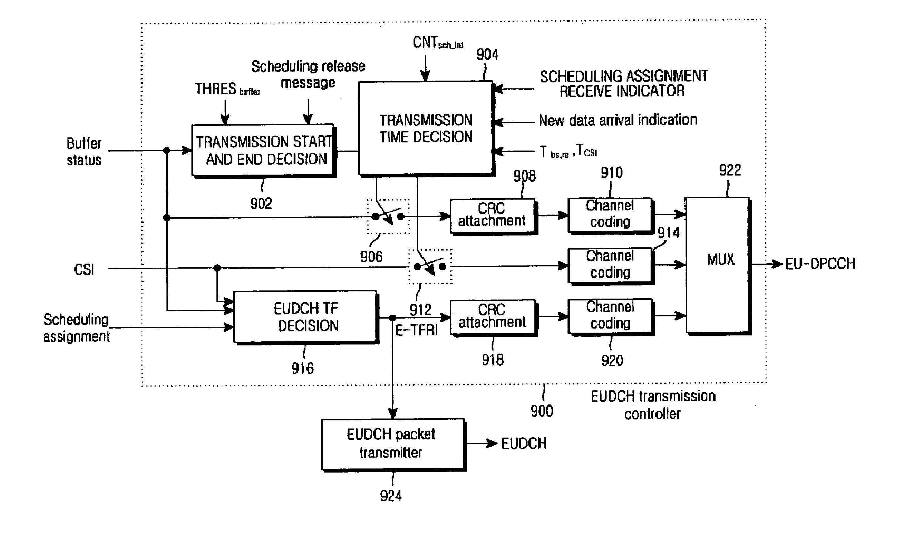
[0085]FIG. 8 illustrates EU-DPCCH signaling for scheduling assignment between the UE and the Node B according to an embodiment of the present invention. Tsch—int denotes a scheduling interval and each scheduling interval is divided into a buffer status information part and a CSI part. CNTsch—int denotes the index of a scheduling interval. Scheduling intervals with CNTsch—int=10 through CNTsch—int=30 are illustrated in FIG. 8. TCSI and Tbs,re denote a CSI transmission interval and a transmission interval of buffer state information, respectively.

[0086] In a scheduling interval 800 with CNTsch—int=10, the UE initially transmits buffer status information and CSI to the Node B, when determining that the amount of packet data stored in the EUDCH data buffer is at least equal to a scheduling threshold. The Node B generates scheduling assignment information based on the buffer status information and the CSI and transmits the scheduling assignment information in a time period 814. An ROT i...

second embodiment

[0113]FIG. 13 illustrates EU-DPCCH signaling for scheduling assignment between the UE and the Node B according to another embodiment of the present invention. Tsch—int denotes a scheduling interval and each scheduling interval is divided into a buffer status information part and a CSI part. CNTsch—int denotes the index of a scheduling interval. TCSI and Tbuffer denote a CSI transmission interval and a transmission interval of buffer state information, respectively.

[0114] In a scheduling interval 1300 with CNTsch—int=10 the UE initially transmits buffer status information and CSI to the Node B, when determining that the amount of packet data stored in the EUDCH data buffer is at least equal to a scheduling threshold THRESbuffer. The Node B generates scheduling assignment information based on the buffer status information and the CSI and transmits the scheduling assignment information in a time period 1314. An ROT is considered in determining the scheduling assignment information.

[0...

third embodiment

[0139] In a third embodiment of the present invention, the RNC controls the transmission times of buffer status information and CSI for a plurality of UEs in order to prevent the increase of the uplink interference caused by uplink signaling. The RNC controls the UEs to transmit buffer status information and CSI in different scheduling intervals. The transmission times of the buffer status information and CSI are calculated by Equation (3) and Equation (4), respectively,

(CNTsch—int−offsetbuffer)mod(Tbuffer / Tsch—int)=0   (3)

(CNTsch—int−offsetCSI)mod(TCSI / Tsch—int)=0   (4)

where mod is an operator that computes the remainder of the division between two operands, CNTsch—int is a scheduling interval index, and offsetbuffer is an integer specific to each UE to prevent a plurality of UEs from providing the EUDCH service from transmitting buffer status information at the same time and thus increasing the measured ROT of the Node B. Each UE transmits the buffer status information to the ...


PUM


Abstract

A method of transmitting and receiving buffer status information and CSI for scheduling of an uplink packet data service in a mobile communication system supporting the uplink packet data service. The buffer status information represents the status of a UE buffer having packet data and the CSI represents the uplink transmit power of a UE. The UE initially transmits the buffer status information and the CSI, if the amount of packet data in the buffer is at least equal to a predetermined threshold. Upon generation of new packet data in the buffer, or according to a predetermined buffer status interval, the UE transmits the buffer status information.

Description

PRIORITY [0001] This application claims priority under 35 U.S.C. § 119 to applications entitled “Method and Apparatus for Assigning Scheduling for Uplink Packet Transmission in a Mobile Communication System” filed in the Korean Intellectual Property Office on Aug. 20, 2003 and assigned Ser. No. 2003-57733, filed in the Korean Intellectual Property Office on Oct. 1, 2003 and assigned Ser. No. 2003-68505, and filed in the Korean Intellectual Property Office on Oct. 7, 2003 and assigned Ser. No. 2003-69740, the contents of all of which are incorporated herein by reference. BACKGROUND OF THE INVENTION [0002] 1. Field of the Invention [0003] The present invention relates generally to a mobile communication system, and in particular, to a method and apparatus for efficiently transmitting and receiving scheduling information and scheduling assignment information for uplink packet transmission. [0004] 2. Description of the Related Art [0005] An asynchronous WCDMA (Wideband Code Division Mul...

Claims


Application Information

Patent Timeline
Patent Type & Authority Applications(United States)
IPC IPC(8): H04L12/28H04W8/24H04W24/10H04W28/00H04W28/14H04W28/26H04W72/04H04W72/12H04W76/02H04W84/12H04W92/10
CPCH04L47/10H04L47/14H04L47/266H04W72/1284H04L47/30H04W28/14H04W72/1252H04L47/29H04W28/02H04W72/52H04W72/21H04W8/04
Inventor LEE, JU-HOKWAK, YONG-JUNCHOI, SUNG-HOHEO, YOUN-HYOUNGKIM, YOUNG-BUMKWON, HWAN-JOON
Owner SAMSUNG ELECTRONICS CO LTD
Why Eureka
Try Eureka