Data receiving device

a data receiving and data technology, applied in the direction of line-transmission details, synchronisation signal speed/phase control, system details, etc., can solve the problem of long transmission distance and high transmission data rate conflict, limited signal attenuation per transmission unit length, and the tendency of reception faults to occur for specific transition patterns. to achieve the effect of stably compensating a high frequency attenuation, low error rate and low power consumption

Inactive Publication Date: 2005-04-21
SONY CORP
View PDF2 Cites 15 Cited by
  • Summary
  • Abstract
  • Description
  • Claims
  • Application Information

AI Technical Summary

Benefits of technology

[0016] According to the present invention, it is possible to stably compensate a high frequency attenuation caused by a differential transmission without being influenced by the transition pattern of NRZ data. Further, it is possible to reproduce proper NRZ data even in the case where skew, which has been generated by delay time difference between positive and negative signals in the differential conductor pair, is large enough to exceed the bit period of the NRZ data. Since a differential receiving circuit is used as the initial stage of the receiving circuit, the data in which common-mode noise has been removed and thus having a low error rate can be received. Further, even in the case where skew amount is unpredictable and widely distributed, the compensation is adaptively performed. For the adaptive compensation, it is unnecessary to provide a transversal filter or threshold control comparator, allowing a data transmission with low power consumption.

Problems solved by technology

In the conductor, there inevitably occurs a limited signal attenuation per unit of transmission length.
Accordingly, a long transmission distance and high transmission data rate conflict with each other.
Therefore, reception fault tends to occur for specific transition pattern such as long string of 0s, which may often appear in actual data.
Since there is a difference in physical length or dielectric constant of coating in the conductor pair by necessity, a limited difference is made also in propagation delay time.
It is said that twist tension control or adjustment at the time of assembling the connector can reduce the skew to about ⅓. However, the skew increases with increasing cable length.
However, even when the above techniques are employed, in order to manufacture the receiving device capable of widely coping with the skew amount that varies depending on the cable, delicate and complicated control needs to be performed so that additional weighting factor of the transversal filter or threshold of the multi-threshold comparator can be properly equalized, in consideration of inter-symbol interference caused by the skew amount and high frequency attenuation due to the aforementioned skin effect.
Therefore, in order to realize a high-speed data transmission, the transversal filter or multi-threshold comparator must be operated at high-speed and with high accuracy, resulting in large power consumption of the receiving device.

Method used


Image

  • Data receiving device
  • Data receiving device
  • Data receiving device

Examples


example 1

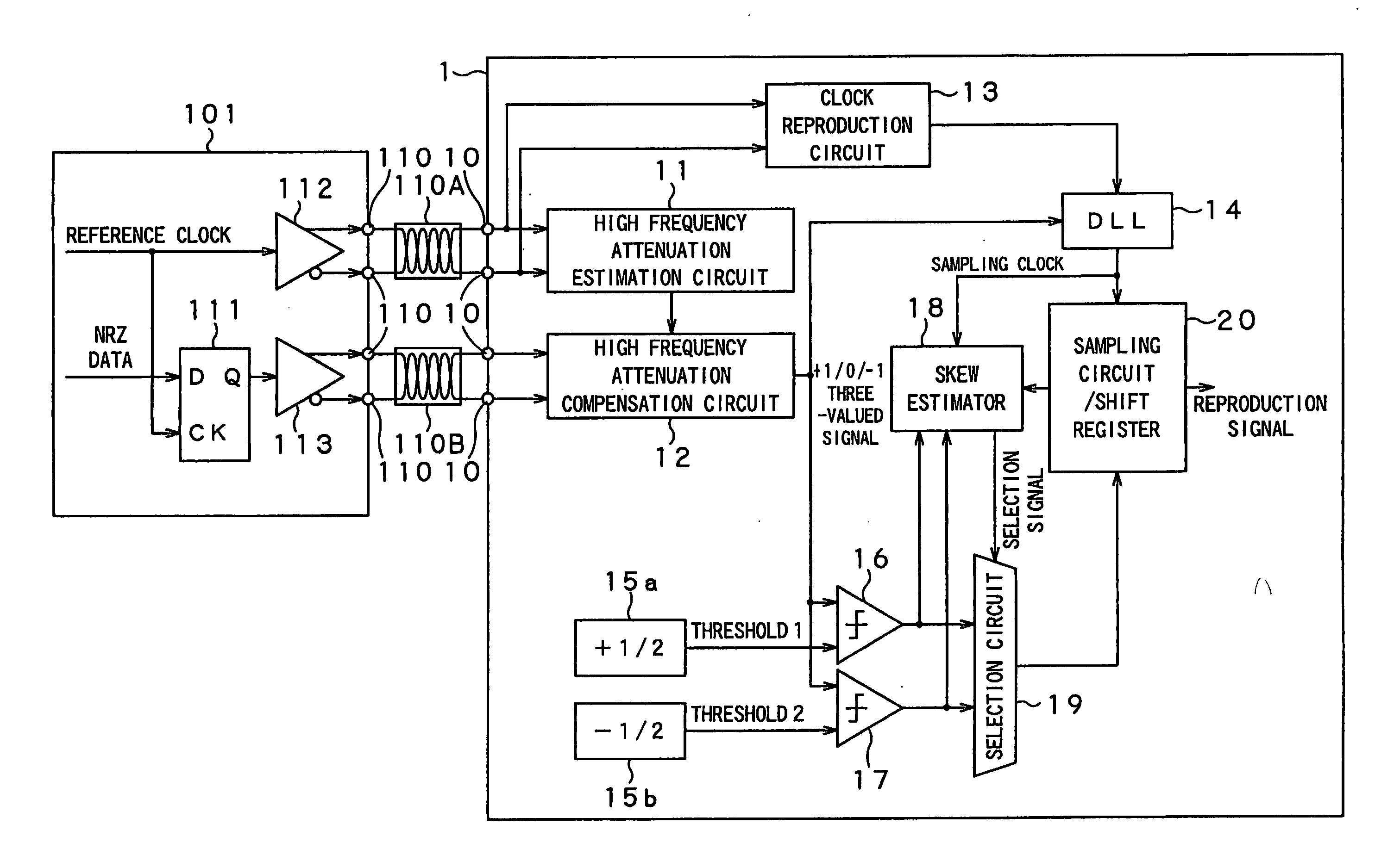
[0044] A concrete example of the present invention will be described in detail with reference to the accompanying drawings. FIG. 3 shows a data receiving device 1 according to the first concrete example of the present invention.

[0045] A data transmitting device 101 that transmits data to a data receiving device 1 outputs NRZ data in synchronization with a reference clock by means of an FF (flip-flop) 111. The amplifiers 112 and 113 amplify the reference clock and NRZ data, respectively, and generate inversion signals. The amplified reference clock and NRZ data are then transmitted to differential conductor pairs (e.g., twisted-pair cable) through a transmitting end 110.

[0046] The data receiving device 1 includes receiving ends 10 to be connected to a differential conductor pair 110A that transmits the reference clock and a differential conductor pair 110B that transmits the NRZ data. The receiving ends of the differential conductor pair 110A are connected to an input of a high fre...

example 2

[0080] A second concrete example of the present invention is shown in FIG. 15. A data receiving device 2 of the second concrete example is featured in that a reference clock is not NRZ data itself, but a signal divided the clock signal by a fixed ratio M, and a multiplication by M circuit 81 is provided in place of the clock reproduction circuit 13. Therefore, a data transmitting device 101 includes an M frequency-division circuit 82 and thereby a clock signal of the NRZ data is frequency-divided by M. In FIG. 15, the same parts as those in FIG. 3 are indicated by the same reference numerals, and the description thereof will be omitted.

[0081]FIG. 16 shows a configuration of a high frequency attenuation characteristics estimation circuit 83 suitably used in the second example. This circuit includes an S / H 84 and S / H 85 that sample the reference clock, in which high frequency attenuation has been compensated, output from the adder 25. The high frequency attenuation characteristics es...


PUM


Abstract

A data receiving device according to the present invention includes a reference clock signal that is transmitted through a differential conductor pair, an estimation means for estimating attenuation characteristics in the differential conductor pair serving as a transmission path of the reference clock signal, and a compensation means for compensating a transmission path attenuation of an NRZ signal based on the estimated attenuation characteristics. Since the reference clock repeats a transition between 0 and 1 at the same period as NRZ data period without fail, it is possible to estimate high frequency attenuation characteristics of a conductor by observing the amplitude of the reference clock at the receiving end. Based on the estimation, characteristic control of a compensation filter is performed with respect to the NRZ signal. Thus, it is possible to reproduce a proper transmission signal from a signal waveform that has been deteriorated by the attenuation caused in a long-distance transmission of high-speed digital data using the differential cable, and propagation skew due to positive and negative asymmetry of the differential pair.

Description

BACKGROUND OF THE INVENTION [0001] 1. Field of the Invention [0002] The present invention relates to a data receiving device, and more specifically, to a data receiving device that reduces influences of a signal attenuation and propagation skew generated when high-speed digital data is transmitted through a differential cable. [0003] 2. Description of the Related Art [0004] A digital data transmission system that propagates, as a differential signal, a clock or NRZ data through paired conductor such as a twisted-pair cable has many advantages: it has a feature of being invulnerable to fluctuation in potential difference of a transceiver, it can eliminate external noise by means of common-mode voltage elimination function of a differential receiving circuit; and it can reduce unnecessary radiation. Therefore, the digital data transmission system is widely used for high-speed data transmission in the medium range (about 10 to 100 meters). [0005] In the conductor, there inevitably occu...

Claims


Application Information

Patent Timeline
Patent Type & Authority Applications(United States)
IPC IPC(8): H04B3/00H04L25/02H04B3/30H04B3/48H04L7/00H04L7/033H04L7/04H04L25/40
CPCH04B3/30H04L7/0338H04L7/0012H04B3/48
Inventor KIKUCHI, HIDEKAZU
Owner SONY CORP
Why Eureka
Try Eureka