
Bone plates

a bone plate and plate body technology, applied in the field of bone plates, can solve the problems of insufficient stabilization of the rib to provide adequate flexural, insufficient purchase of bone screws, and disadvantages of rib fixation by plating techniques

Active Publication Date: 2005-04-21
ELLIS THOMAS J +2
View PDF99 Cites 281 Cited by
  • Summary
  • Abstract
  • Description
  • Claims
  • Application Information

AI Technical Summary

Problems solved by technology

Each of these plating techniques may have disadvantages for rib fixation.
For example, these techniques may not sufficiently stabilize the rib to provide adequate flexural and torsional support for the rib at the fracture site.
Bone screws may not achieve adequate purchase in ribs to stabilize a bone plate because ribs are relatively thin and their bone density is low.
Wires, suture material, and / or prongs also may not offer sufficient bone plate stabilization because they are not rigid enough.
Each of these plating techniques thus may permit movement at the fracture with each breath, causing substantial pain and compromising the healing process.
Furthermore, wires, suture material, and / or prongs may press on and damage a neurovascular bundle disposed on the inferior surface of ribs, if these fasteners are placed over this bundle during bone plate installation.
Placement of these fasteners between the neurovascular bundle and bone still may damage the bundle and generally increases the time in surgery.

Method used


Image

  • Bone plates
  • Bone plates
  • Bone plates

Examples


example 1

Bone Plates with a Multi-Aperture Spanning Portion

[0092] This example describes exemplary bone plates having a spanning portion with a plurality of apertures. The apertures may be arranged so that a clip component can be assembled with and secured to a spanning portion at two or more positions along the spanning portion.

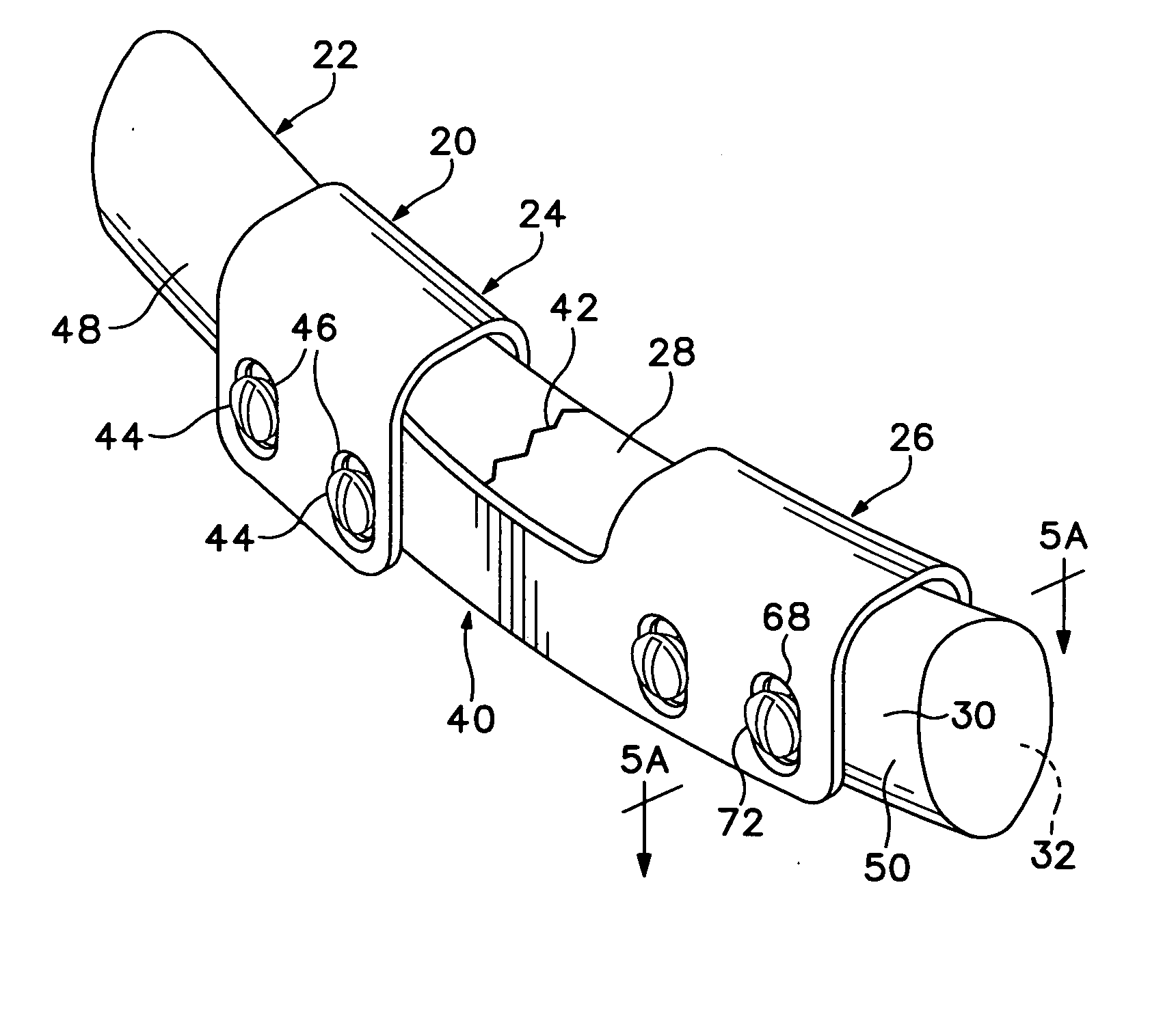
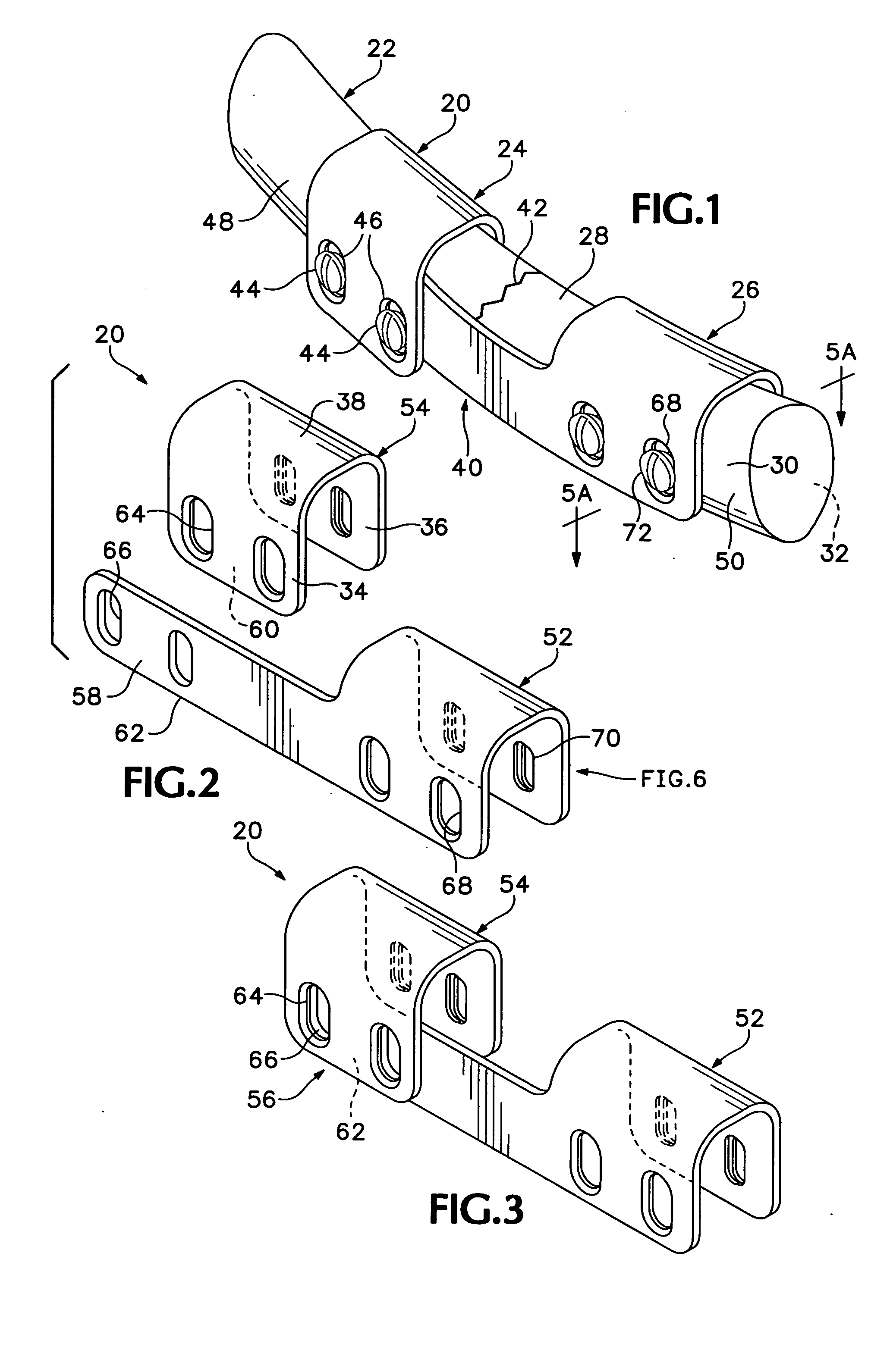
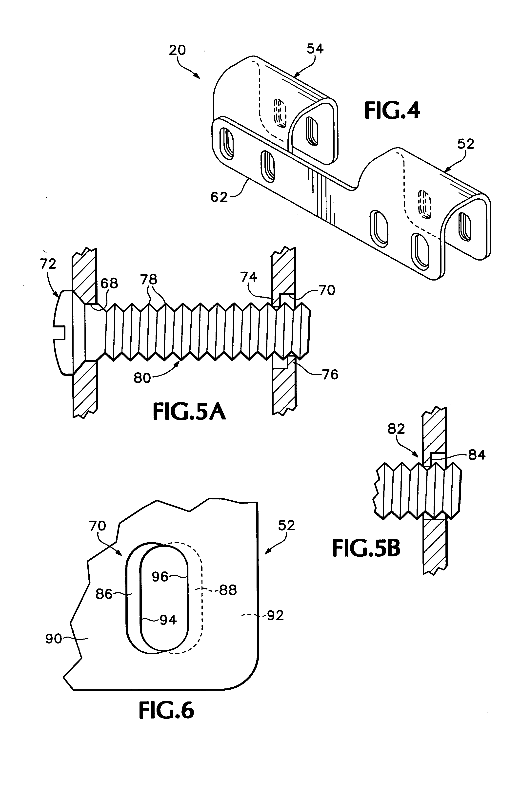
[0093]FIG. 14 shows an exemplary bone plate 210 for fixing a fractured rib bone. The bone plate may include a spanning component 212 having a spanning portion 214 and a first clip portion 216 formed unitarily. The bone plate also may include one or more additional clip portions, such as clip components 218, 220 formed as separate components.

[0094] Spanning portion 214 may include a plurality of spanning apertures 222 arrayed along the length of this portion. Spanning apertures 222, and particularly subsets of these apertures, may be configured to be aligned with one or more clip apertures 224 of each clip portion. In the present illustration, adjacent pairs of the...

example 2

Bone Plates with Arrays of Plate Components

[0098] This example describes bone plates that may be assembled as arrays of plate components.

[0099]FIG. 15 shows a bone plate 240 including a tandem array of spanning components 242, 244 that overlap and can be secured to one another with fasteners received in aligned apertures, shown at 246. Each spanning component may include a clip portion and a spanning portion. Any suitable number of spanning components, of similar or distinct configuration, may be arrayed. One or more clip components may be secured to a spanning component, or the bone plate may lack a distinct clip component.

example 3

Bone Plates of Unitary Construction

[0100] This example describes exemplary bone plates having a unitary construction.

[0101]FIG. 16 shows an exemplary bone plate 260 for fixing a fractured rib. Bone plate 260 may be formed as one component, so that a spanning portion 262 is joined to, and flanked by, clip portions 264, 266.


PUM


Abstract

Systems, including methods, apparatus, and kits, for fixing bones, such as rib bones, with bone plates.

Description

CROSS-REFERENCE TO PRIORITY APPLICATION [0001] This application is based upon and claims the benefit under 35 U.S.C. § 119(e) of the following U.S. provisional patent applications: Ser. No. 60 / 498,866, filed Aug. 28, 2003; and Ser. No. 60 / 548,685, filed Feb. 26, 2004. These applications are incorporated herein by reference in their entirety for all purposes.BACKGROUND [0002] The human skeleton is composed of 206 individual bones that perform a variety of important functions, including support, movement, protection, storage of minerals, and formation of blood cells. These bones can be grouped into two categories, the axial skeleton and the appendicular skeleton. The axial skeleton consists of 80 bones that make up the body's center of gravity, and the appendicular skeleton consists of 126 bones that make up the body's appendages. The axial skeleton includes the skull, vertebral column, ribs, and sternum, among others, and the appendicular skeleton includes the long bones of the upper...

Claims


Application Information

Patent Timeline
IPC IPC(8): A61BA61B17/56A61B17/80
CPCA61B17/8076Y10S606/905Y10S606/904A61B17/8033
Inventor ELLIS, THOMAS J.GILLARD, JOELHORST, STEVEN P.
Owner ELLIS THOMAS J
Learn More