Prosthetic valve for implantation in a body vessel

a technology for prosthetic valves and body vessels, applied in vein valves, medical science, blood vessels, etc., can solve the problems of loss of effectiveness, physical manifestations and pathology, and introduction of temporary reverse flow direction in the vessel

Active Publication Date: 2005-04-21
COOK MEDICAL TECH LLC
View PDF18 Cites 409 Cited by
  • Summary
  • Abstract
  • Description
  • Claims
  • Application Information

AI Technical Summary

Benefits of technology

[0009] In one exemplary embodiment, a prosthetic valve according to the invention comprises first and second tubular frame members and a graft member disposed between the frame members. The second tubular frame member is circumferentially disposed around the first tubular frame member. The graft member forms a valve that permits fluid flow through a body vessel in a first direction and substantially prevents fluid flow through the body vessel in a second, opposite direction.
[0010] In another exemplary embodiment, a prosthetic valve according to the invention comprises first and second tubular frame members and a graft member disposed between the frame members. The first tubular frame member defines axially-extending extension points and the second tubular frame member is circumferentially disposed around the first tubular frame member. The graft member is attached to the extension points of the first tubular frame member and forms a valve that permits fluid flow through a body vessel in a first direction and substantially prevents fluid flow through the body vessel in a second, opposite direction.

Problems solved by technology

Varying fluid pressures over time, however, can introduce a temporary reverse flow direction in the vessel.
While natural valves may function for an extended time, some may lose effectiveness, which can lead to physical manifestations and pathology.
For example, venous valves are susceptible to becoming insufficient due to one or more of a variety of factors.
Over time, the vessel wall may stretch, affecting the ability of the leaflets to close.
Furthermore, the natural valve leaflets may become damaged, such as by formation of thrombus and scar tissue, which may also affect the ability of the valve leaflets to close.
Once a valve is damaged, venous valve insufficiency may be present, and can lead to discomfort and possibly ulcers in the legs and ankles.

Method used


Image

  • Prosthetic valve for implantation in a body vessel
  • Prosthetic valve for implantation in a body vessel
  • Prosthetic valve for implantation in a body vessel

Examples


Embodiment Construction

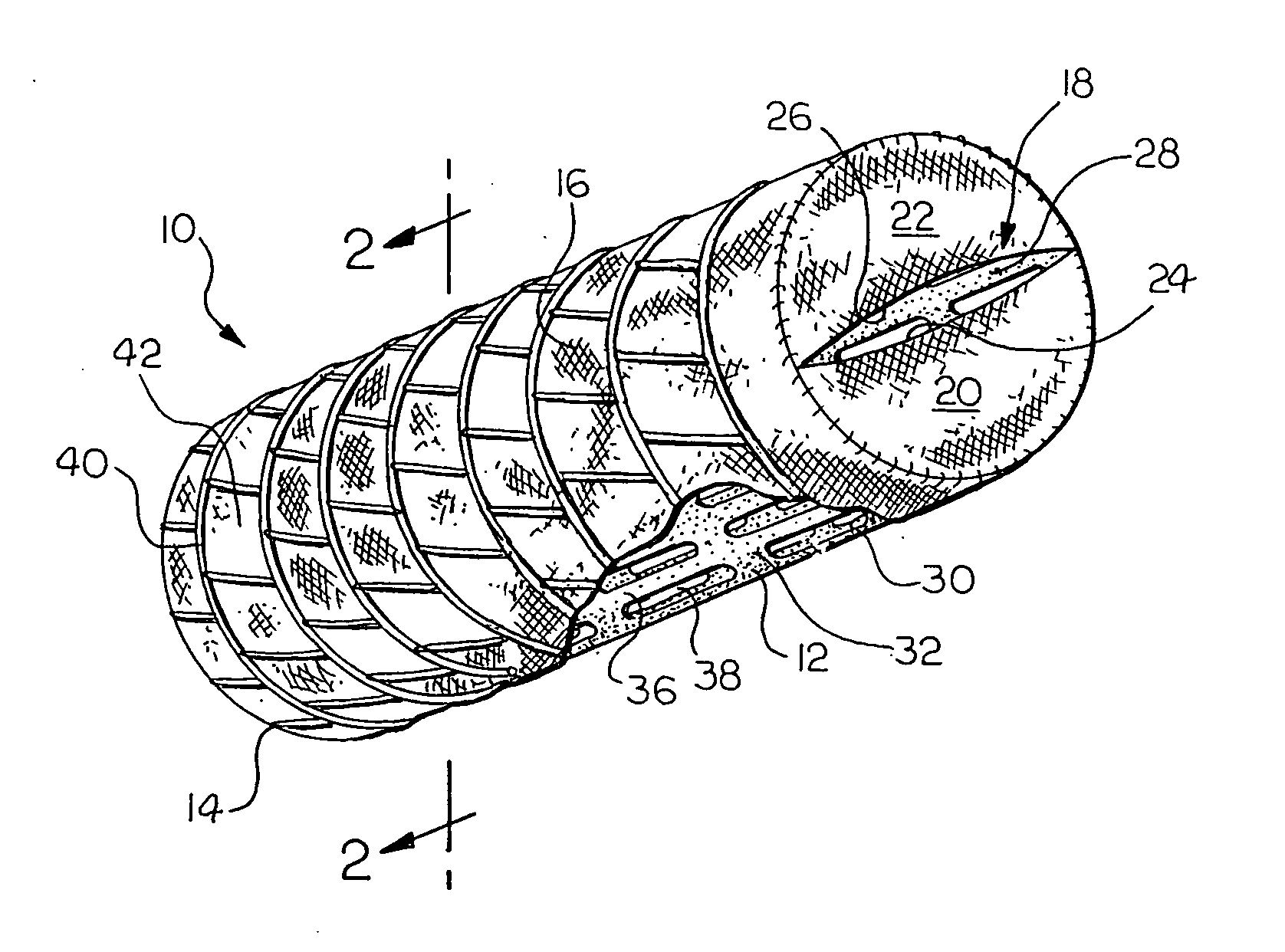
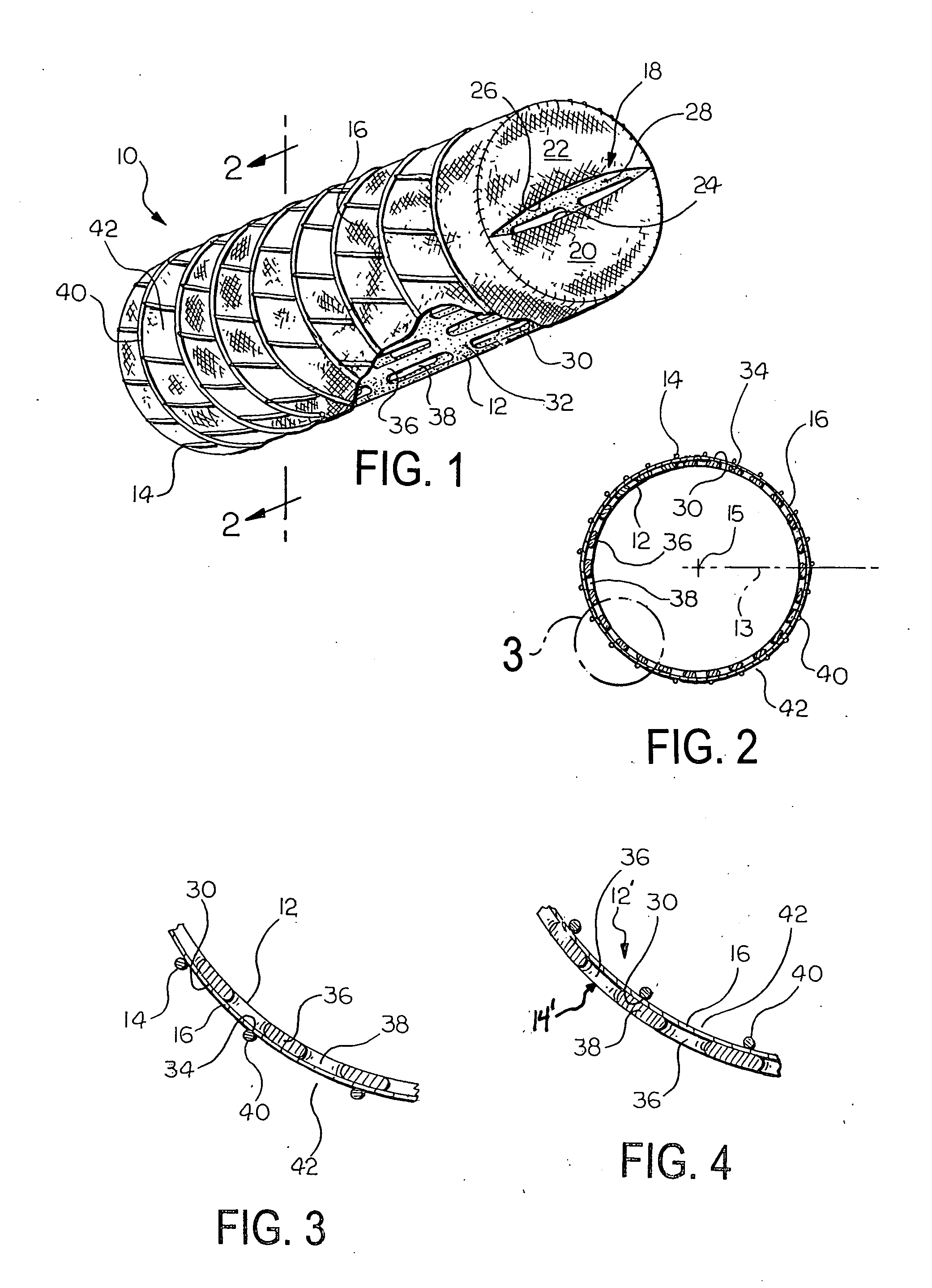
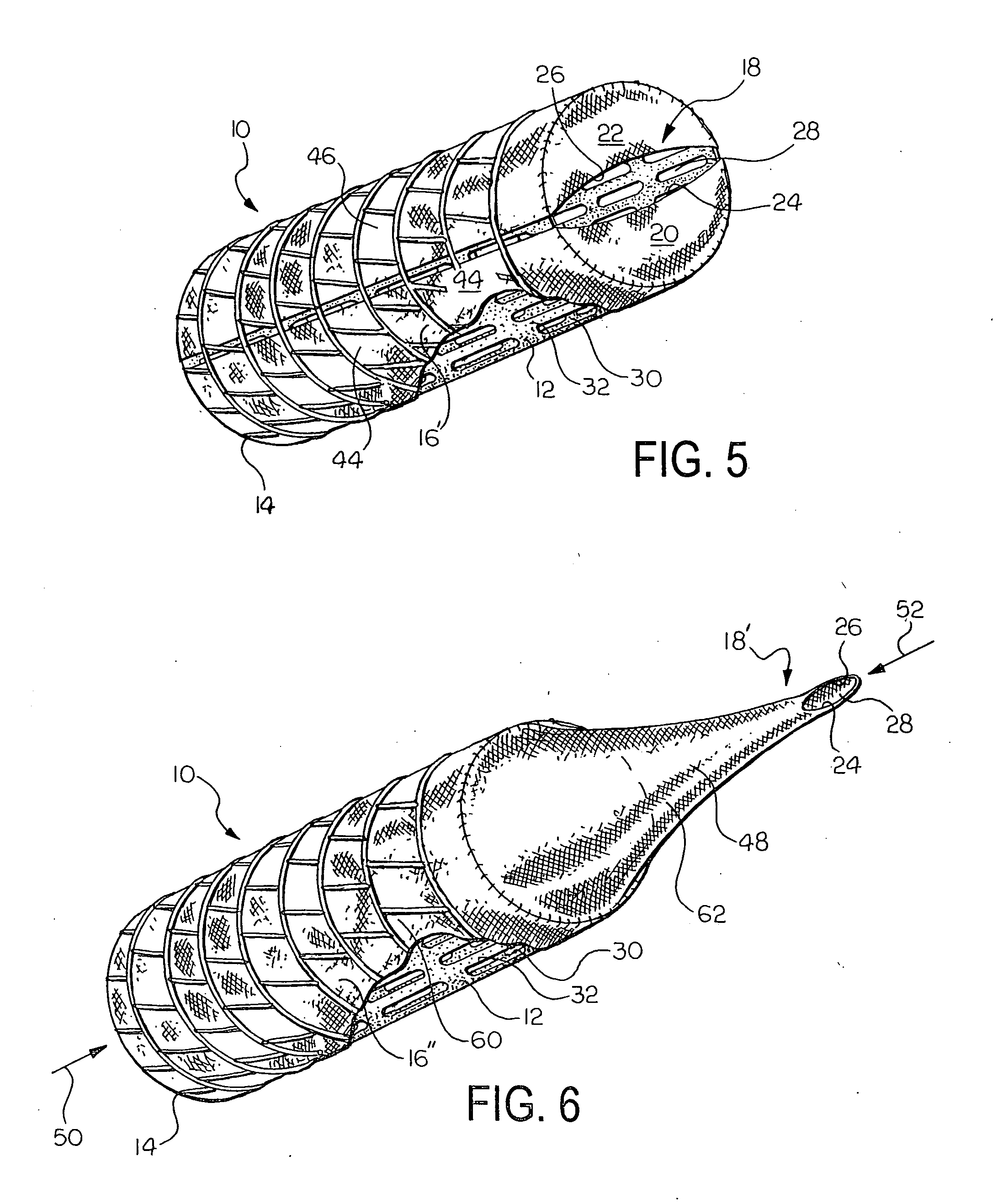
[0008] The invention provides medical devices for implantation in a body vessel. Medical devices according to exemplary embodiments of the invention comprise first and second frame members and a graft member forming a valve that permits fluid flow through a body vessel in a first direction, and substantially prevents fluid flow through the body vessel in a second, opposite direction At least a portion of the graft member is disposed between the frame members.

[0009] In one exemplary embodiment, a prosthetic valve according to the invention comprises first and second tubular frame members and a graft member disposed between the frame members. The second tubular frame member is circumferentially disposed around the first tubular frame member. The graft member forms a valve that permits fluid flow through a body vessel in a first direction and substantially prevents fluid flow through the body vessel in a second, opposite direction.

[0010] In another exemplary embodiment, a prosthetic ...


PUM


Abstract

Prosthetic valves for implantation in a body vessel are provided. Prosthetic valves according to the invention comprise first and second frame members and a graft member at least partially disposed between the first and second frame members. The graft member forms a valve that permits fluid flow through the body vessel in a first direction and substantially prevents fluid flow through the body vessel in a second, opposite direction.

Description

CROSS-REFERENCE TO RELATED APPLICATION [0001] This application claims priority to U.S. Provisional Application Ser. No. 60 / 491,745 filed on Jul. 31, 2003. The entire disclosure of which is hereby incorporated into this disclosure in its entirety.FIELD OF THE INVENTION [0002] The invention relates to implantable medical devices. More specifically, the invention relates to prosthetic valves for implantation in a body vessel. BACKGROUND OF THE INVENTION [0003] Many vessels in animals transport fluids from one bodily location to another. Frequently, fluid flows in a unidirectional manner long the length of the vessel. Varying fluid pressures over time, however, can introduce a temporary reverse flow direction in the vessel. In some vessels, such as mammalian veins, natural valves are positioned along the length of the vessel and act as one-way check valves that open to permit the flow of fluid in the desired direction, and quickly close upon a change in pressure, such as a transition fr...

Claims


Application Information

Patent Timeline
Patent Type & Authority Applications(United States)
IPC IPC(8): A61F2/06A61F2/24A61F2/90
CPCA61F2/2418A61F2/2475A61F2250/0063A61F2230/008A61F2220/0016A61F2230/0067A61F2230/0078A61F2220/0008
Inventor CASE, BRIAN C.OSBORNE, THOMAS A.FLAGLE, JACOB A.PARKER, FRED T.
Owner COOK MEDICAL TECH LLC
Why Eureka
Try Eureka