
Method and apparatus for obtaining high integrity and availability in multi-channel systems

a multi-channel system and high integrity technology, applied in the field of multi-channel systems, can solve problems such as fail-passive computer architecture to generic errors

Active Publication Date: 2005-04-21
THE BOEING CO
View PDF21 Cites 46 Cited by
  • Summary
  • Abstract
  • Description
  • Claims
  • Application Information

AI Technical Summary

Benefits of technology

[0009] In accordance with one aspect of the present invention, the two computation lanes of the Actuation Control Electronics select the digi...

Problems solved by technology

With dual-dissimilar processors the computer architecture is fail-passive to generic errors.

Method used


Image

  • Method and apparatus for obtaining high integrity and availability in multi-channel systems
  • Method and apparatus for obtaining high integrity and availability in multi-channel systems
  • Method and apparatus for obtaining high integrity and availability in multi-channel systems

Examples


Embodiment Construction

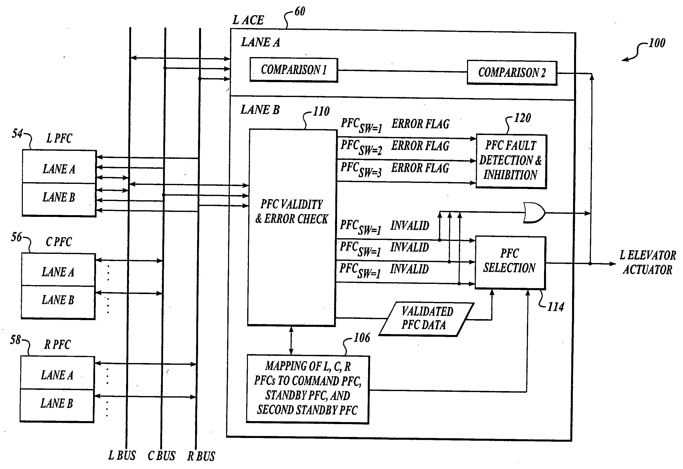
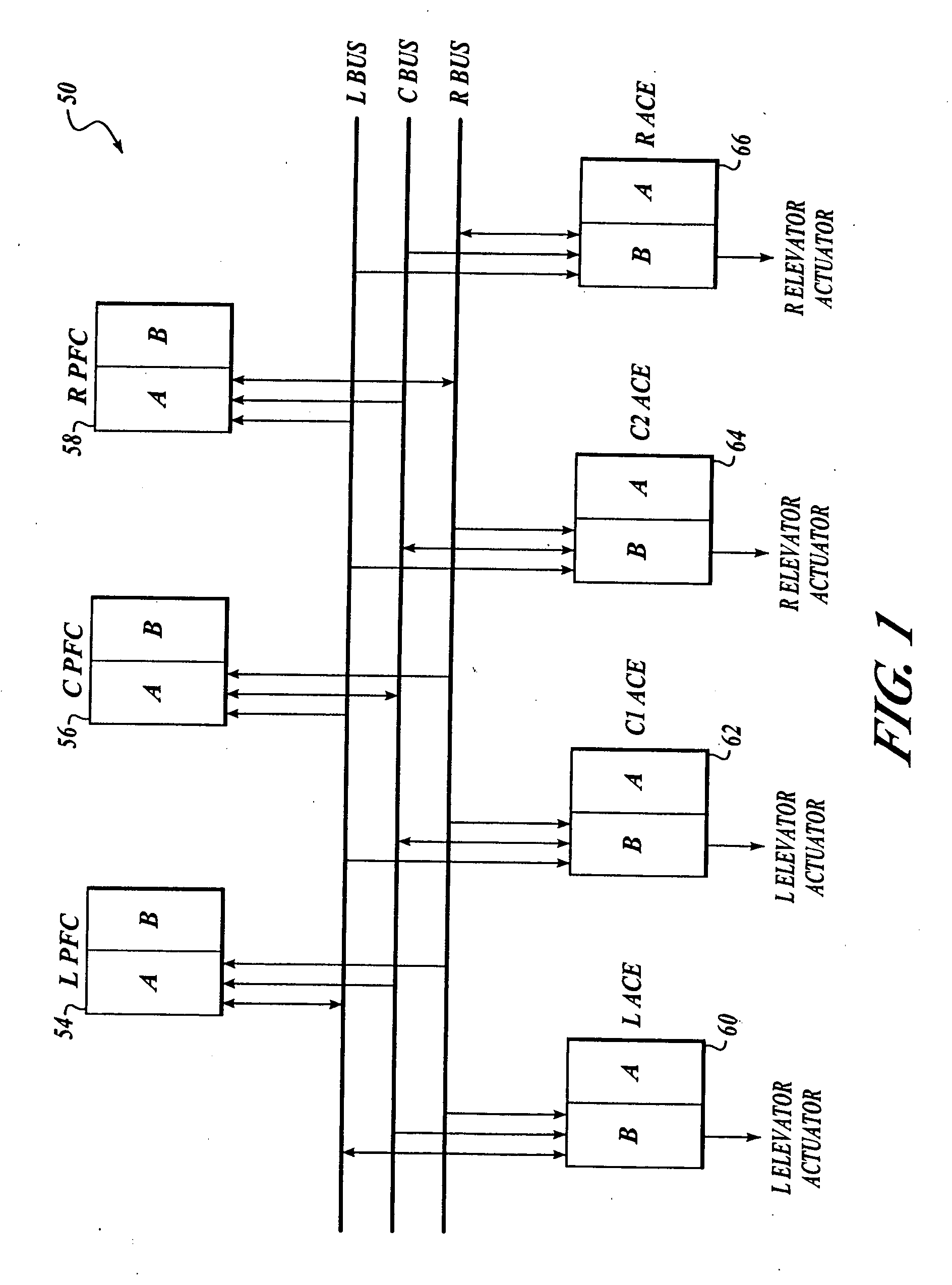
[0016] As shown in FIG. 1, an embodiment of the present invention includes a system 50 having at least two PFCs 54-58 and at least three actuation control electronics line replaceable units (LRU) (hereinafter ACE) 60-66. Each of the PFCs 54-58 and ACEs 60-66 include dual-dissimilar self-monitoring processing lanes A and B. Each lane is a separate computer system. Each pair of dissimilar lanes A and B in each of the PFCs 54-58 and ACEs 60-66 is synchronized. However, the lanes A and B between different PFCs and ACEs may be asynchronous.

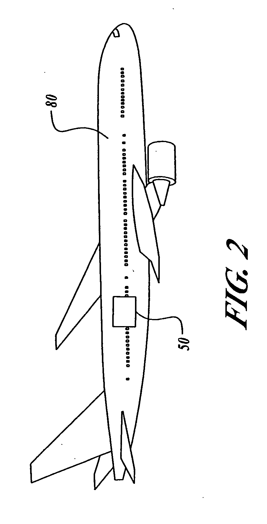
[0017] The ACEs 60-66 monitor the lane A and B outputs of the PFCs 54-58 and inhibit PFCs if the monitoring indicates persistent PFC errors. As shown in FIG. 2, an airplane 80 embodying the system 50 includes two elevator actuators on each of the left and right elevator control surfaces. The ACEs 60-66 are matched on a one-to-one basis with the four elevator actuators. It will be appreciated that if the airplane 50 is designed with three elevator actu...


PUM


Abstract

Systems and methods for asynchronous multi-channel data communications are provided. An embodiment of the invention includes a minimum of three channels for digital computation in Primary Flight Computers and four channels for digital / analog conversion in Actuation Control Electronics. Each channel (Primary Flight Computer or Actuation Control Electronics) contains two computation lanes with dissimilar processors and compilers. Hence with dual-dissimilar processors the computer architecture is fail-passive to generic errors. The two Actuation Control Electronics computation lanes select the digital control data of one of the two computation lanes of one of the three digital computation channels for conversion and transmission to associated actuators.

Description

FIELD OF THE INVENTION [0001] This invention relates generally to multi-channel systems and, more specifically, to fault tolerance in multi-channel systems. BACKGROUND OF THE INVENTION [0002] Prior to the advent of fly-by-wire technology, flight control surfaces on a commercial aircraft were controlled using a complex system of cables and mechanical controls. Since the advent of fly-by-wire technology, such mechanical control systems were replaced with systems having no direct mechanical couplings between pilot controls and flight control surfaces. Instead of using mechanical couplings such as cables, a fly-by-wire system including pilot control transducers senses the position of the pilot controls and generates electrical signals proportional to the position of the pilot controls. The electrical signals are combined with other airplane data in a primary flight computer to produce a flight control surface command that controls movement of the flight control surfaces of the aircraft....

Claims


Application Information

Patent Timeline
IPC IPC(8): B64C13/42B64C13/50G06F19/00
CPCB64C13/42G05D1/0077B64C13/503B64C13/505
Inventor YEH, YING CHIN
Owner THE BOEING CO
Learn More