Back end of line clone test vehicle

a test vehicle and back end technology, applied in the direction of basic electric elements, semiconductor/solid-state device testing/measurement, instruments, etc., can solve the problems of difficult to predict what artifacts are discovered on an inspected layer and might produce killer defects in the next layer

Active Publication Date: 2005-04-21
PDF SOLUTIONS INC
View PDF16 Cites 18 Cited by
  • Summary
  • Abstract
  • Description
  • Claims
  • Application Information

AI Technical Summary

Benefits of technology

[0007] One aspect of the present invention is a test vehicle, comprising at least one product layer having at least one product circuit pattern thereon, and one or more clone layers formed over the product layer. The one or more clone layers include a plurality of structures from the group consisting of clone test vehicle circuit patterns and clone test vehicle vias. The presence of one or more defects in the one or more clone layers is an indicator of a tendency of the product circuit pattern to impact yield of a succeeding layer to be formed over the product circuit pattern in a product.
[0008] Another aspect of the invention is a method for designing or fabricating a plurality of different test vehicles, in which the improvement comprises designing or fabricating the plurality of test vehicles, so that: each test vehicle has a respectively different product layer having at least one product circuit pattern thereon; each test vehicle has one or more clon

Problems solved by technology

In the case of full flow TV's, the prior art does not disclose how to identify the detailed interaction of defects in adjacent (vertical) levels through the results of electrical testing.
For the case of the identification of defect

Method used


Image

  • Back end of line clone test vehicle
  • Back end of line clone test vehicle
  • Back end of line clone test vehicle

Examples


Embodiment Construction

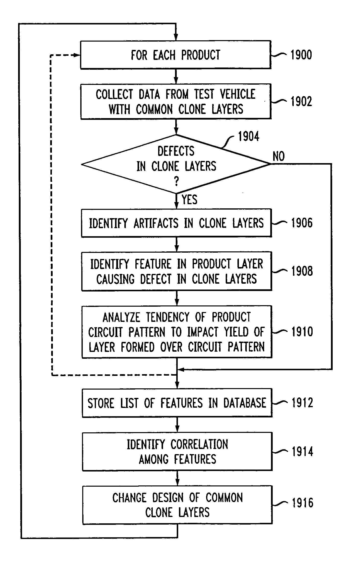
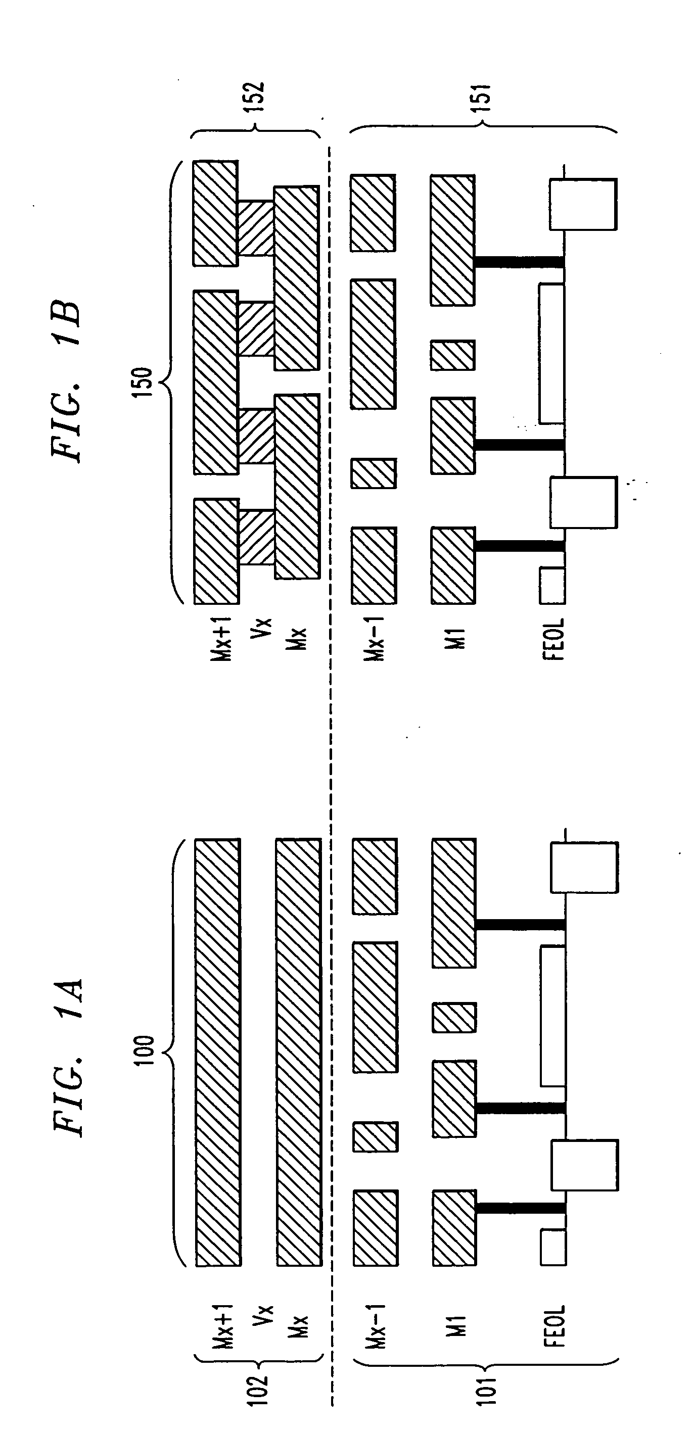
[0028] The exemplary method pertains to the fabrication of integrated circuits, and more particularly to methods that characterize and quantify classes of structural features that propagate defects through their interaction with an adjacent (vertical) layer within the multi-levels of integrated circuit structures. The example provides a gateway to three-dimensional measurements of structures in a circuit pattern that result in killer defects ill subsequently deposited pattern layers.

[0029] This exemplary method uses geometrical pattern variables of one level (the “clone layer”) that interact with an actual product layer immediately below the clone layer. This technique can identify specific structural features (“aggressors”) of the product layer that can induce defects into a given susceptible geometrical pattern contained in the TV clone layer variables. In some cases, an artifact in the product layer may not be measurable in a single-layer test vehicle, but the same artifact can ...


PUM


Abstract

A test vehicle comprises at least one product layer having a east one product circuit pattern on the product layer, and one or more clone layers formed over the product layer (1902). The one or more clone layers include a plurality of structures, which may include clone test vehicle circuit patterns and/or clone test vehicle vias (1902). The presence of one or more defects (1904) in the one or more clone layers (1908) is an indicator of a tendency of the product circuit pattern to impact yield of a succeeding layer to be formed over the product circuit pattern in a product (1910).

Description

[0001] This application claims the benefit of U.S. Provisional Patent Application 60 / 360,304, filed Feb. 28, 2002, which is incorporated by reference herein in its entirety.FIELD OF THE INVENTION [0002] The present invention fabrication of integrated circuits generally, and more specifically to methods of characterizing defects that impact wafer yield, and their causes. BACKGROUND OF THE INVENTION [0003] In the past two decades, sophisticated systems have evolved in the techniques to evaluate defects that affect the yield of integrated circuits. These systems include yield models generated in conjunction with the design of test vehicles (TV) that facilitate both yield prediction and yield enhancement of an integrated circuit manufacturing process. Except for the measurement of contact yields, (short flow) TV structures are utilized to evaluate defects on a single level. [0004] In the case of full flow TV's, the prior art does not disclose how to identify the detailed interaction of ...

Claims


Application Information

Patent Timeline
IPC IPC(8): H01L21/027H01L21/66H01L23/544
CPCH01L22/20H01L22/34H01L2924/0002H01L2924/00
Inventor CIPLICKAS, DENNIS J.HESS, CHRISTOPHER
Owner PDF SOLUTIONS INC
Why Eureka
Try Eureka