Interface method for a device driver

US20050086632A1Inactive Publication Date: 2005-04-21OKUMA CORP

Image

  • Interface method for a device driver
  • Interface method for a device driver
  • Interface method for a device driver

Examples


Embodiment Construction

[0041] In the following, embodiments of the present invention will be described with reference to the accompanied drawings.

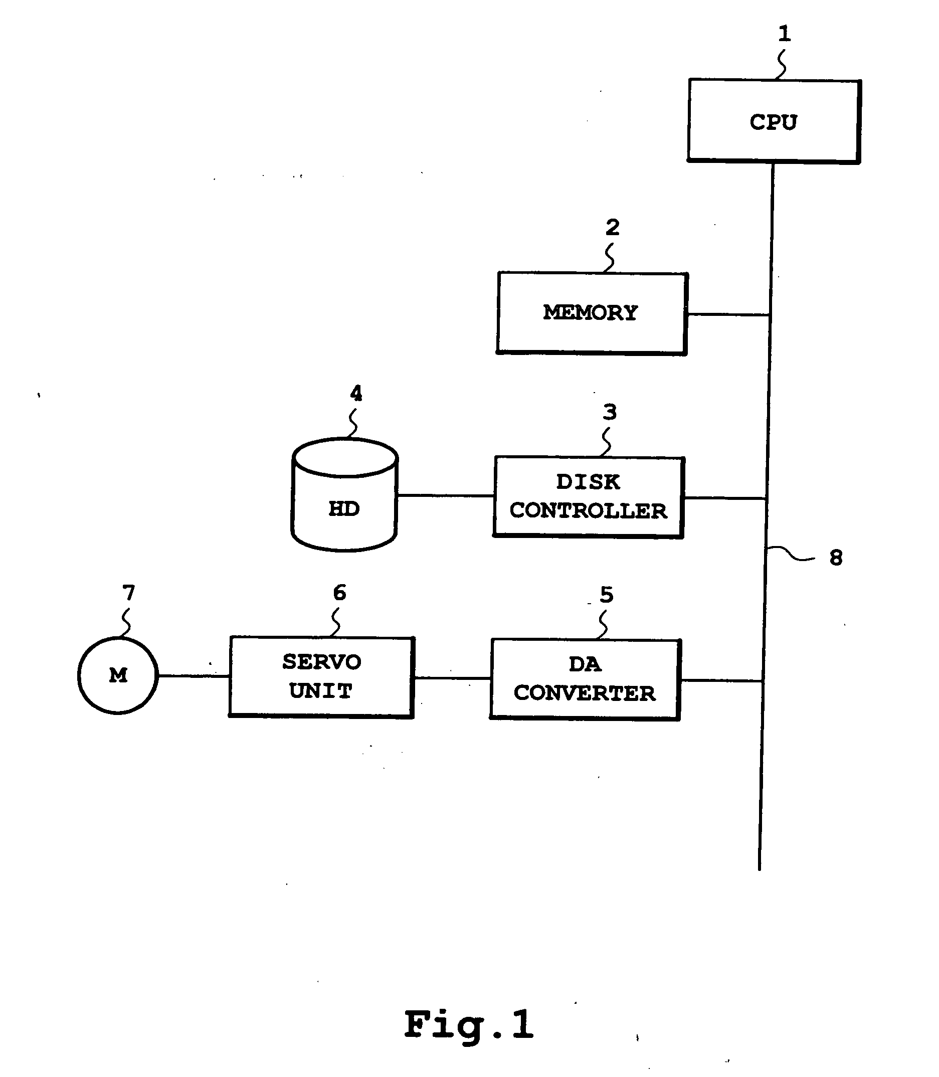
[0042]FIG. 1 is a block diagram showing an example of a device for implementing the present invention. A CPU (Central Processing Unit) 1 is connected, via a system bus 8, to a memory 2, a disk controller 3, and a DA converter 5, and the DA converter 5 is connected, via a servo unit 6, to a servo motor 7. The CPU 1 incorporates a memory management unit (not shown) to support a plurality of memory spaces, and to allocate, and manage, in different memory spaces, an application program, which is stored in the hard disk 4 and loaded to the memory 2 to be executed by the CPU 1, and a device driver program, which is implemented as being stored in the memory space in the operating system where the kernel is held. The operating system is stored in the hard disk 4 and loaded to the memory 2 to be executed by the CPU 1.

[0043] As a control program for the DA converter 5 i...


PUM


Abstract

An interface method for a device driver for enabling a function call initiated by an application program and addressed to a device driver side, and the reverse. The present invention provides a means for perform device control in an operation system in which an application program and a device driver are stored in different memory spaces. The operation control is achieved utilizing a method for enabling a function call, using an IDL (interface definition language), initiated from an application program and addressed to a dynamic link library. The present invention additionally provides a means for enabling a function call initiated from a device driver and addressed to an application program. According to the present invention, an interface for device control is defined using an IDL, and a program for relaying a function call between an application program and a device driver is provided so as to enable a function call initiated by an application program and addressed to the device drive, and vice versa. The relay program is automatically created using a special IDL compiler.

Description

CROSS-REFERENCE TO RELATED APPLICATION(S) [0001] The entire disclosure of Japanese Application No. 2003-343279 including specification, claims, drawings and abstract is incorporated herein by reference in its entirety. BACKGROUND OF THE INVENTION [0002] 1. Field of the Invention [0003] The present invention relates to a computer system having an operating system installed therein, wherein an application program and a kernel are held in different memory spaces and a driver program for controlling an input / output device is held in the memory space where the kernel is held, and a mechanism for enabling a call initiated from the application program, of a function provided by a dynamic link library or other application programs, based on an interface defined in an interface definition language (hereinafter referred to as an IDL). In particular, the present invention relates to application of this mechanism between the application program and the device driver program so as to enable a ca...

Claims


Application Information

Patent Timeline
21 Apr 2005
Publication
US20050086632A1
IPC
G06F13/10; G06F9/40; G06F9/44; G06F9/46
CPC
G06F9/545
Inventors
OYAMA, HIROSHI