Disk driving device

a technology of a drive device and a disc drive, which is applied in the direction of data recording, information storage, instruments, etc., can solve the problems of increasing the number of parts, increasing the complexity of the structure, and affecting the operation of the device, so as to prevent the dislocation of the pick-up position and prevent the operation of errors

Inactive Publication Date: 2005-04-21
SHINWA KK
View PDF4 Cites 10 Cited by
  • Summary
  • Abstract
  • Description
  • Claims
  • Application Information

AI Technical Summary

Benefits of technology

[0019] Since the unloading side trigger mechanism stops the pick-up by moving the first slider from the second position, positional dislocation of the pick-up is prevented when a disc is not loaded.
[0020] Further, the disc drive device of the present invention includes a return

Problems solved by technology

In disc players of this structure, a problem of operational instability occurs because a neutral point is generated in the transmission of the drive force at which the drive force of the drive gear is not transferred from the idler gear to both the loading mechanism and the pick-up moving mechanism during the rotation of the idler plate.
Therefore, in a conventional disc player structure, a problem of operational instability occurs because a neutral point is generated in the drive force transmission at which the drive force of the drive gear is not transferred from the idler gear to both the loading mechanism and the pick-up

Method used


Image

  • Disk driving device
  • Disk driving device
  • Disk driving device

Examples


Embodiment Construction

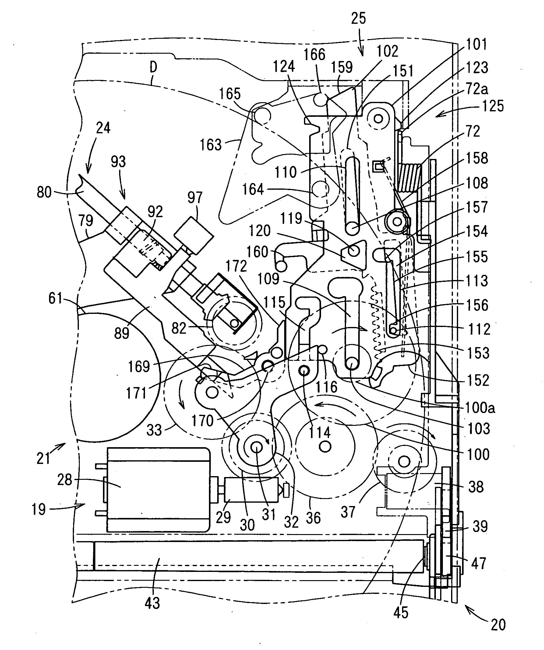
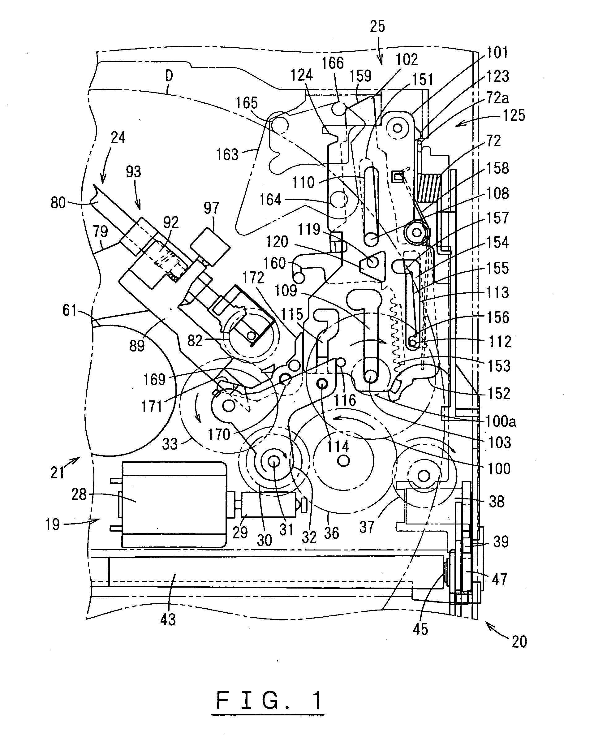
[0041] An embodiment of the present invention is described hereinafter with reference to the drawings.

[0042] The disc accommodated by the disc player using the disc drive device of the present invention may be, for example, a compact disc for music reproduction, and the example used in the following description is an album-type 12 cm disc.

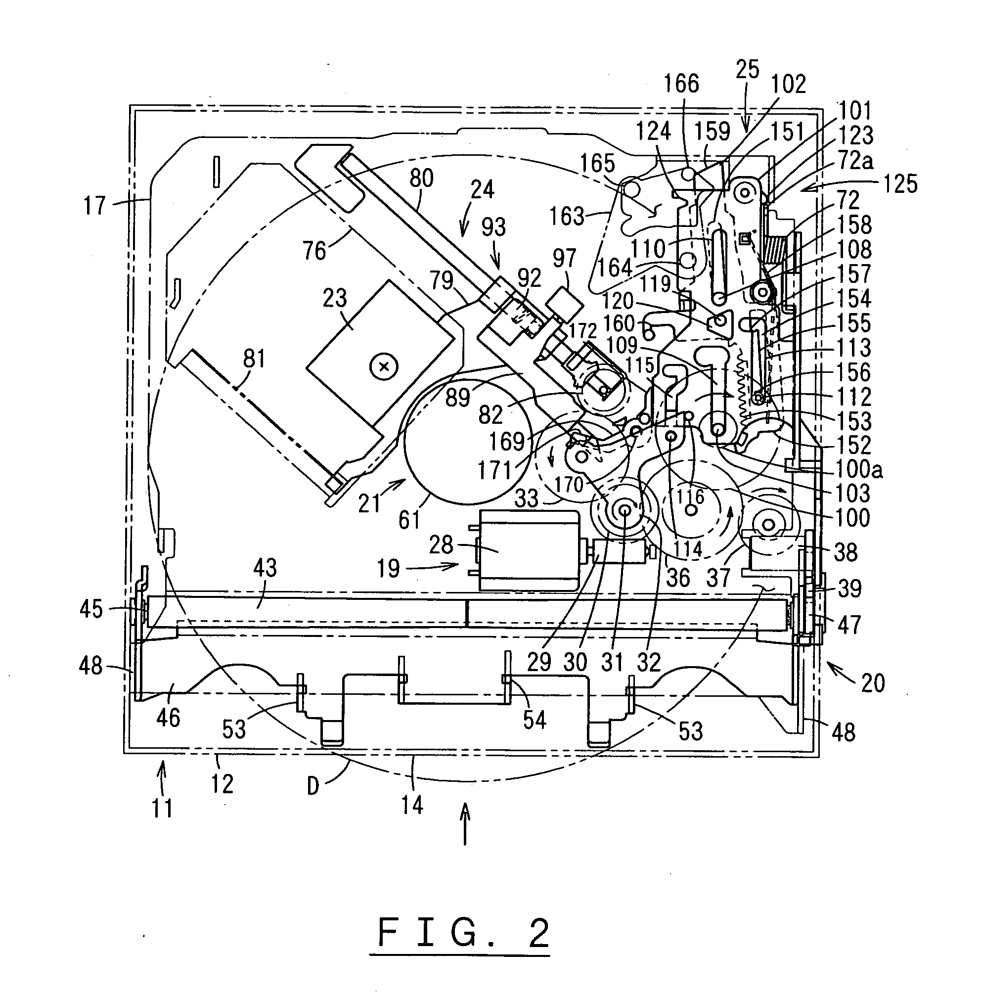
[0043] In FIGS. 2 and 3, reference number 11 refers to the body of a disc player. The body 11 has a chassis 12 and a cover 13 mounted on the top surface of the chassis 12. A disc insertion elongated hole 14 is formed on the front side for inserting and removing a disc D in a horizontal orientation. In the following description, the disc insertion elongated hole 14 side of the body 11 in FIG. 2 is referred to as the front, the side opposite that of the disc insertion elongated hole 14 is referred to as the back, and the sides across from the disc insertion elongated hole 14 are referred to as the right side and the left side.

[0044] A base 17 is s...


PUM


Abstract

A drive gear (30) is rotated by a motor (28). Drive force from a loading transmission gear (36), which constantly engages the drive gear (30), is constantly transmitted to a loading mechanism (20). In a pick-up moving mechanism (24), an idler gear (33), which constantly engages the drive gear (30), engages a pick-up transmission gear (82) to transmit drive force. The movement of a first slider (101) engages and disengages the idler gear (33) and the pick-up transmission gear (82). The first slider (101) is located at a first position when a disc (D) is not loaded, and is located at a second position when the disc (D) is loaded. A loading mechanism (20) ends a loading operation by moving the first slider (101) to a second position. The transmission and switching of drive force from a single motor to the loading mechanism (20) and the pick-up moving mechanism (24) is ensured.

Description

TECHNICAL FIELD [0001] The present invention relates to a disc drive device for driving a loading mechanism and pick-up moving mechanism using a single motor. BACKGROUND ART [0002] In the conventional art, for example, among disc players for compact discs used to reproduce music and the like, there are known to be disc players that reduce the number of motors by using a drive switching mechanism to selectively drive a loading mechanism and pick-up moving mechanism using a single motor, as is disclosed, for example, in Japanese Laid-Open Patent Publication No. 2000-298903. [0003] This disc player is provided with an idler plate, which is rotatable about the axis of a drive gear that is rotated by drive force from a motor and which functions as a drive switching mechanism. The idler plate is rotated to a disc loading position for transmitting drive force to the loading mechanism or to a pick-up moving position for transmitting drive force to the pick-up moving mechanism in accordance ...

Claims


Application Information

Patent Timeline
IPC IPC(8): G11B7/085G11B17/051G11B17/04G11B21/02
CPCG11B7/08582G11B21/02G11B17/051G11B17/05
Inventor SHIMOZAKI, MITSUHIRO
Owner SHINWA KK
Why Eureka
Try Eureka