Combined solar and wind powered rotor mechanism

a rotor mechanism and solar energy technology, applied in wind motors with solar radiation, renewable energy generation, greenhouse gas reduction, etc., can solve the problems of no effective devices and energy output productivity, and achieve the effect of increasing the speed of the admitted air and facilitating i

Inactive Publication Date: 2005-04-28
ROYER GEORGE R
View PDF7 Cites 15 Cited by
  • Summary
  • Abstract
  • Description
  • Claims
  • Application Information

AI Technical Summary

Benefits of technology

[0006] More directly, the subject apparatus is generally adapted to have means therein to admit outside air into the chamber so that the solar heat generated in the chamber will help accelerate through convection mean or otherwise to move such air admitted into the chamber to facilitate and increase the speed of the admitted air into the chamber and thence out of the air outlet opening onto the rotor blades.

Problems solved by technology

In this area of energy conversion, there are no effective devices structured to alternately and simultaneously capture solar energy and wind energy as distinct and separate driving forces so as to capitalize on both such energy sources to drive a common separate rotor mechanisms, thereby increasing the energy output productivity of the apparatus.

Method used


Image

  • Combined solar and wind powered rotor mechanism
  • Combined solar and wind powered rotor mechanism
  • Combined solar and wind powered rotor mechanism

Examples


Embodiment Construction

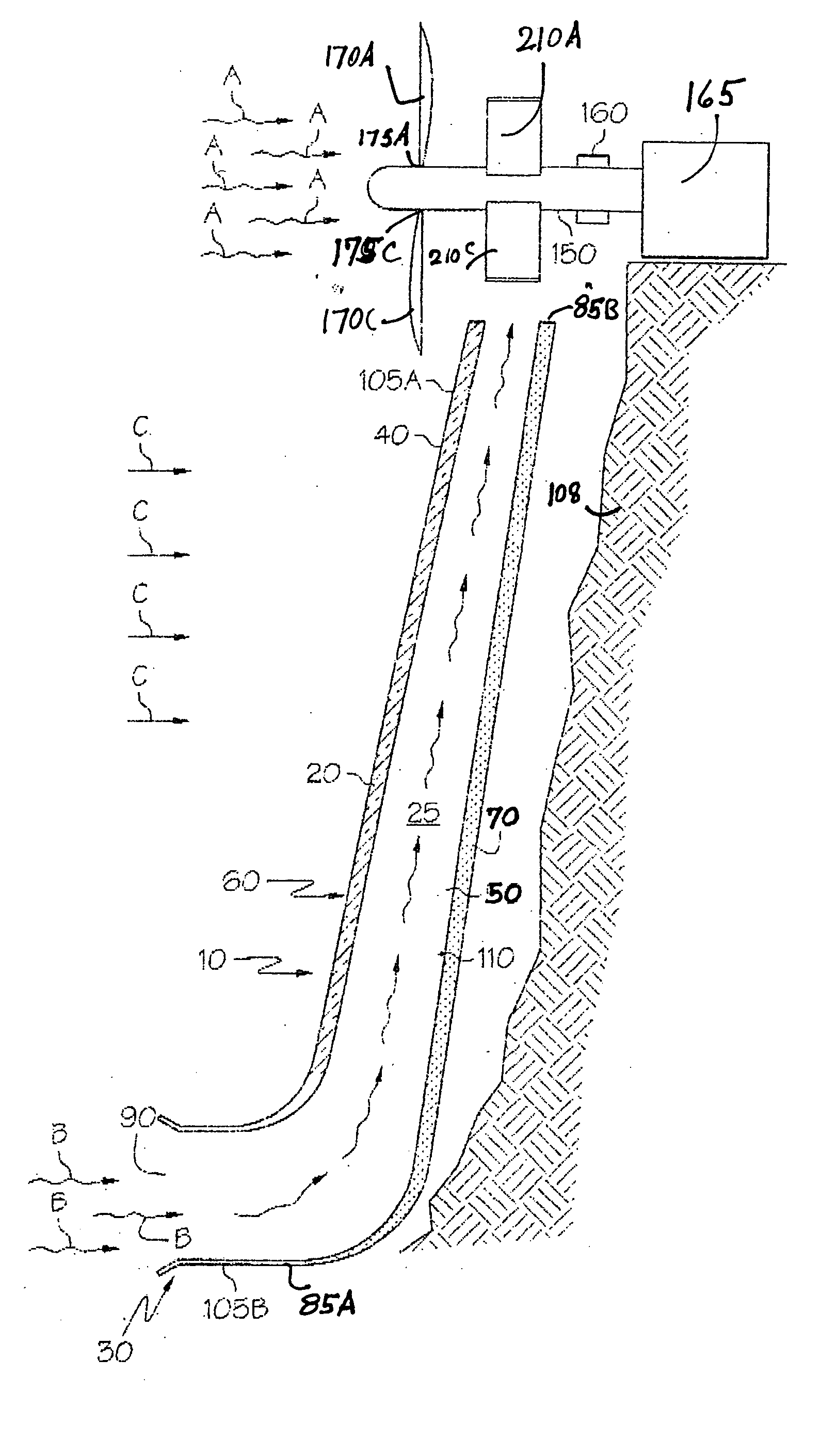
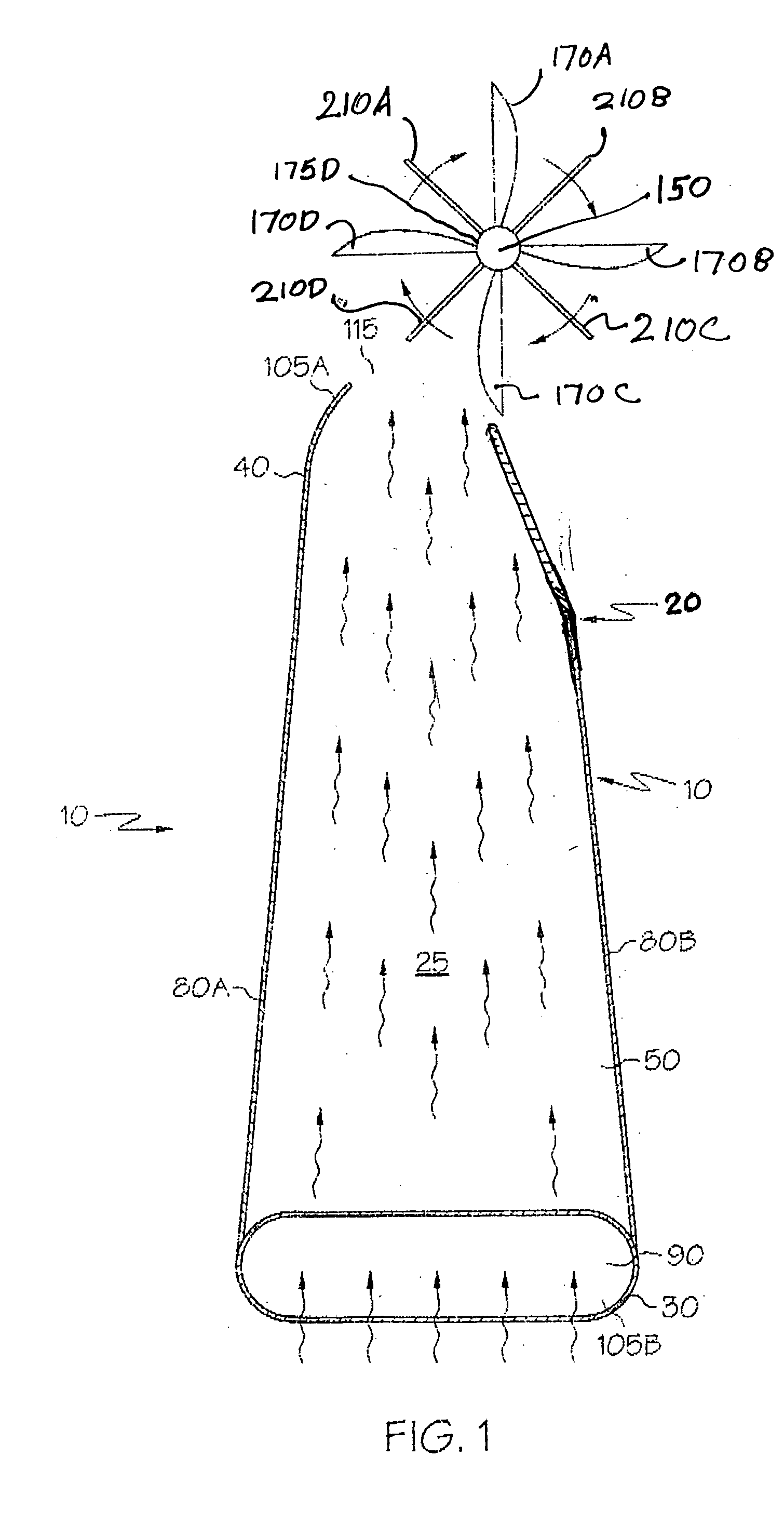
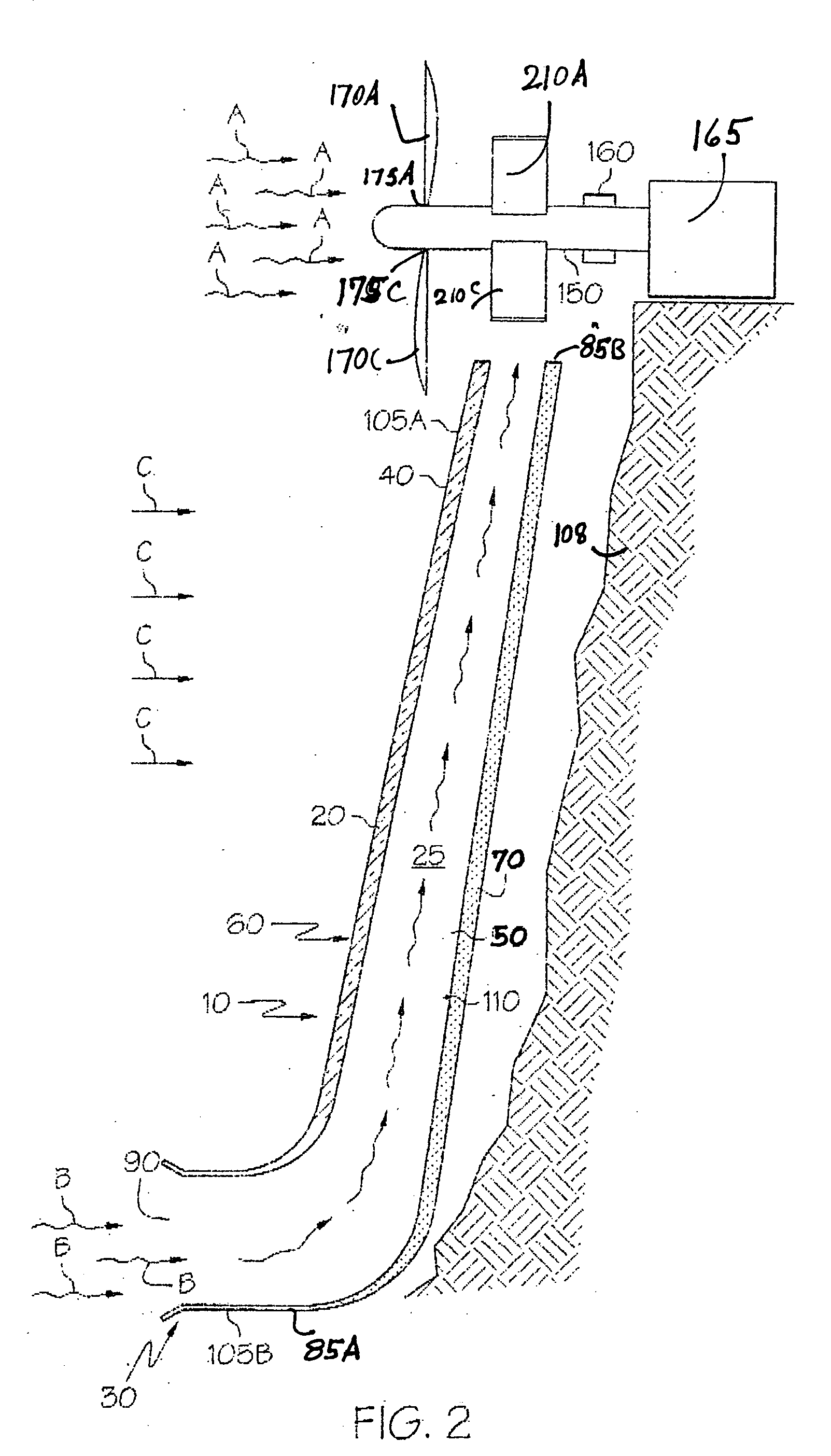
[0018] The subject apparatus which incorporates features of the subject invention is a combined wind powered and solar powered rotor mechanism, specifically utilizing energy from both solar and wind sources to provide energy to drive a rotor mechanism, such apparatus comprising in its general form a vertically standing or substantially upright housing structure that has an air intake opening at the bottom portion or at some position intermediate between the bottom portion and upper portion of the apparatus, such opening connecting outside air with a central longitudinally extending chamber in such housing structure that extends upwardly towards the upper part of the apparatus, with a portion of the apparatus being comprised of translucent material to admit sun light into the longitudinal extending chamber with a portion of the chamber being formed of solar absorption materials to receive solar energy from such sun light, with an air driven rotor mechanism at or near the upper portio...


PUM


Abstract

The subject apparatus which incorporates features of the subject invention is a combined wind powered and solar powered rotor mechanism, specifically utilizing energy from both solar and wind sources to provide energy to drive a rotor mechanism, such apparatus comprising in its general form a vertically standing or substantially upright structure that has an air intake opening at the bottom portion or at some position intermediate between the bottom portion and upper portion of the apparatus, such opening connecting outside air with a central longitudinally extending chamber that extends upwardly towards the upper part of the apparatus, with a portion of the apparatus, in one embodiment, being comprised of translucent material to admit solar energy into the longitudinal extending chamber with a portion of the chamber, in one embodiment, being formed of solar absorption materials to receive solar energy, with an air powered rotor mechanism at or near the upper portion of the chamber, such rotor mechanism having a central rotational axle rotationally installed through or adjacent to such chamber, such rotational axle having air movement sensitive means to receive the impact of any upwardly extending air moving through such chamber and additionally having air movement sensitive means disposed on a portion of such rotational axle to receive directly air from outside such chamber, for direct rotational drive of such rotational axle.

Description

KNOWN PRIOR ART [0001] There are several known devices that utilize solar generated heat. DISCUSSION OF PRIOR ART AND BACKGROUND OF INVENTION [0002] Energy conversion devices can potentially utilize both solar and wind to drive a rotor mechanism for ultimate energy generated for usage in mechanical, electrical or other form. Devices incorporating features using solar energy indirectly and direct wind power to drive a rotor mechanism would be economical and environmentally harmless, specifically using both wind and solar energy. [0003] More directly means to combine the driving force of both air movement and solar heat so that both such energy sources are utilized directly or indirectly to drive a rotor or similar such mechanism would augment energy output. In this area of energy conversion, there are no effective devices structured to alternately and simultaneously capture solar energy and wind energy as distinct and separate driving forces so as to capitalize on both such energy so...

Claims


Application Information

Patent Timeline
Patent Type & Authority Applications(United States)
IPC IPC(8): F03D1/04F03D9/00F03G6/04
CPCF03D1/04F03D9/007F03G6/045Y02E10/72F05B2260/24Y02E10/465F05B2240/131Y02E10/46Y02E10/74Y02T10/7072F03D1/025F03D3/0427F03D9/25F03D80/70
Inventor ROYER, GEORGE R.
Owner ROYER GEORGE R
Why Eureka
Try Eureka