

Motor Protector
a motor protector and protector technology, applied in the direction of positive displacement liquid engines, piston pumps, borehole/well accessories, etc., can solve the problems of motor protector run-life damage, wear of motor protector components, etc., and achieve the effect of reducing the effect of sand on the run-life of the protector
- Summary
- Abstract
- Description
- Claims
- Application Information
AI Technical Summary
Benefits of technology
Problems solved by technology
Method used
Image

Examples
Embodiment Construction
[0013] In the following description, numerous details are set forth to provide an understanding of the present invention. However, it will be understood by those of ordinary skill in the art that the present invention may be practiced without these details and that numerous variations or modifications from the described embodiments may be possible.
[0014] The present invention generally relates to a system and method for reducing detrimental effects of sand on motor protectors. The system and method are useful with, for example, a variety of downhole production systems, such as electric submersible pumping systems. However, the devices and methods of the present invention are not limited to use in the specific applications that are described herein.
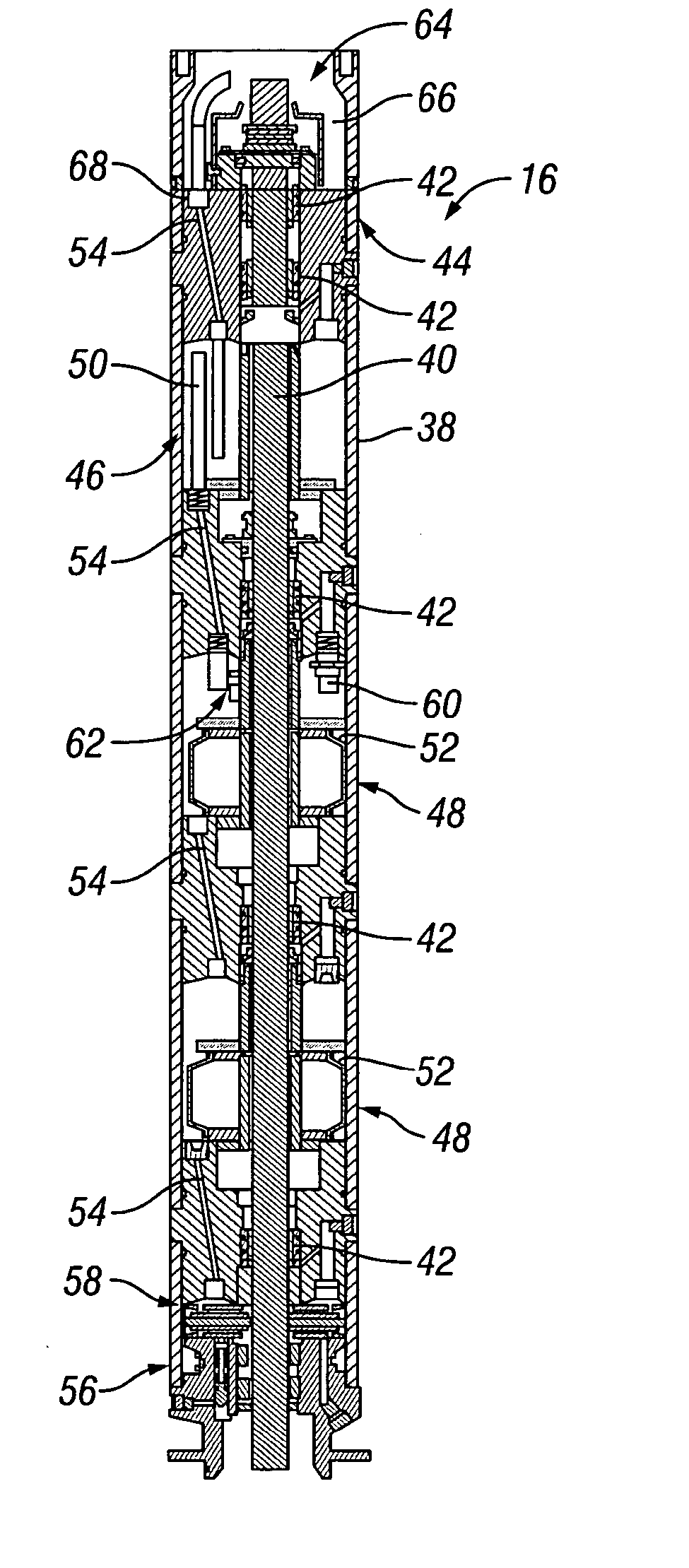
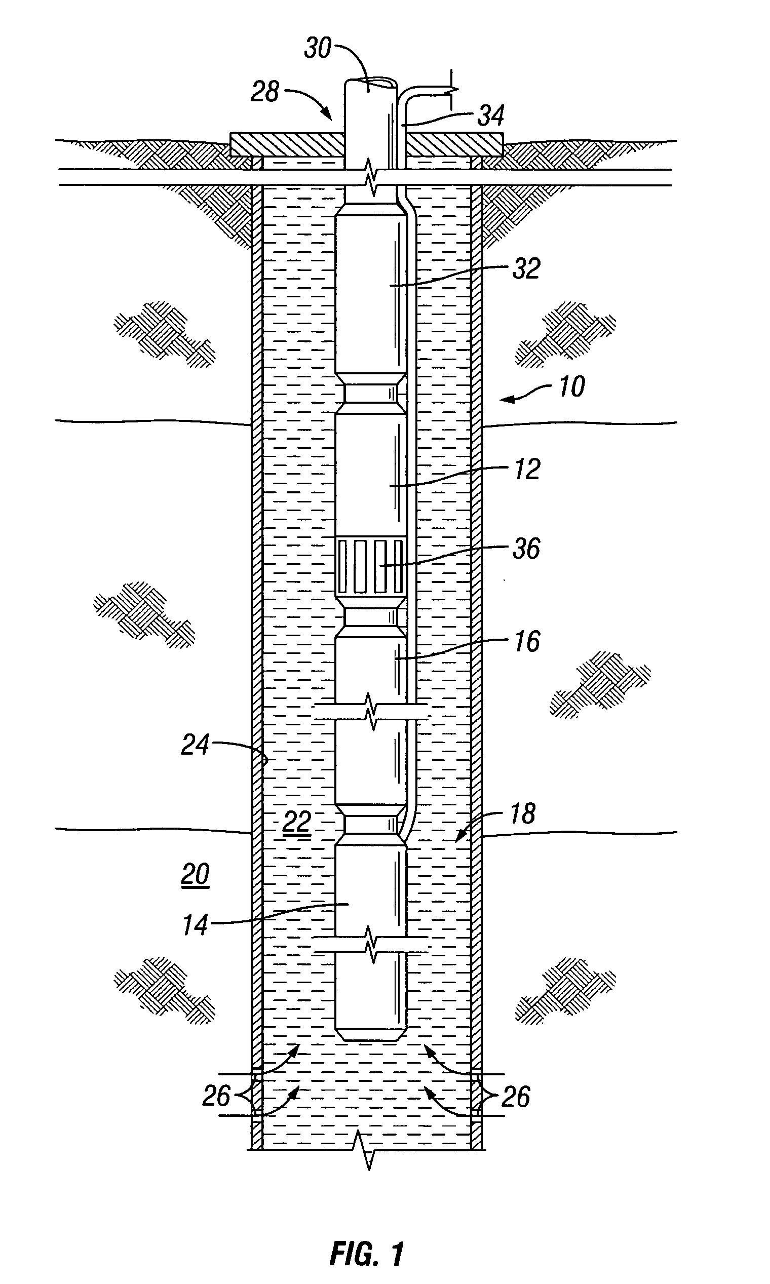
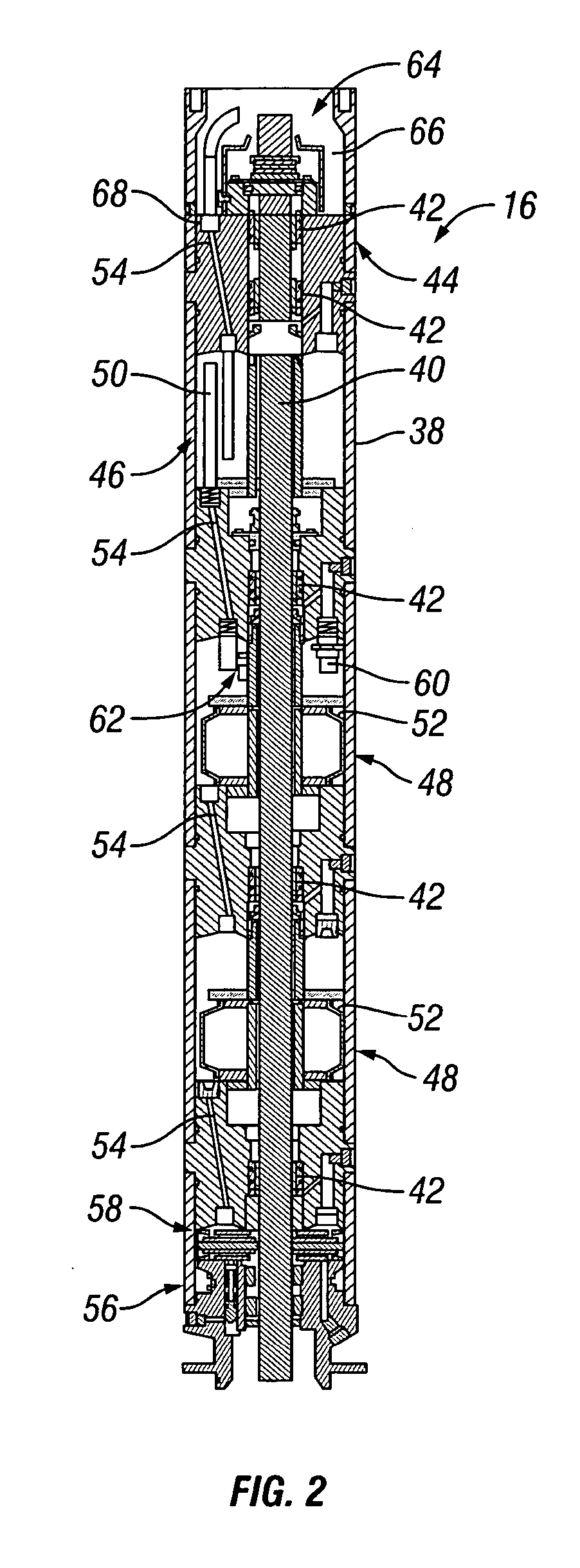
[0015] Referring generally to FIG. 1, an example of a pumping system 10, such as an electric submersible pumping system, is illustrated according to an embodiment of the present invention. Pumping system 10 may comprise a variety of comp...
PUM
 Abstract
Description
Claims
Application Information