Active stability wheel chair based on positive angle sensors

a positive angle sensor and active stability technology, applied in the field of motor vehicles, can solve the problems of corrupting the signal of the accelerometer, using three orthogonal positioned accelerometers, and not being robust enough

Inactive Publication Date: 2005-04-28
SUNRISE MEDICAL HHC INC
View PDF5 Cites 25 Cited by
  • Summary
  • Abstract
  • Description
  • Claims
  • Application Information

AI Technical Summary

Problems solved by technology

The means of determining slope using three orthogonally positioned accelerometers, as described above, is a non-robust methodolog

Method used


Image

  • Active stability wheel chair based on positive angle sensors
  • Active stability wheel chair based on positive angle sensors
  • Active stability wheel chair based on positive angle sensors

Examples


Embodiment Construction

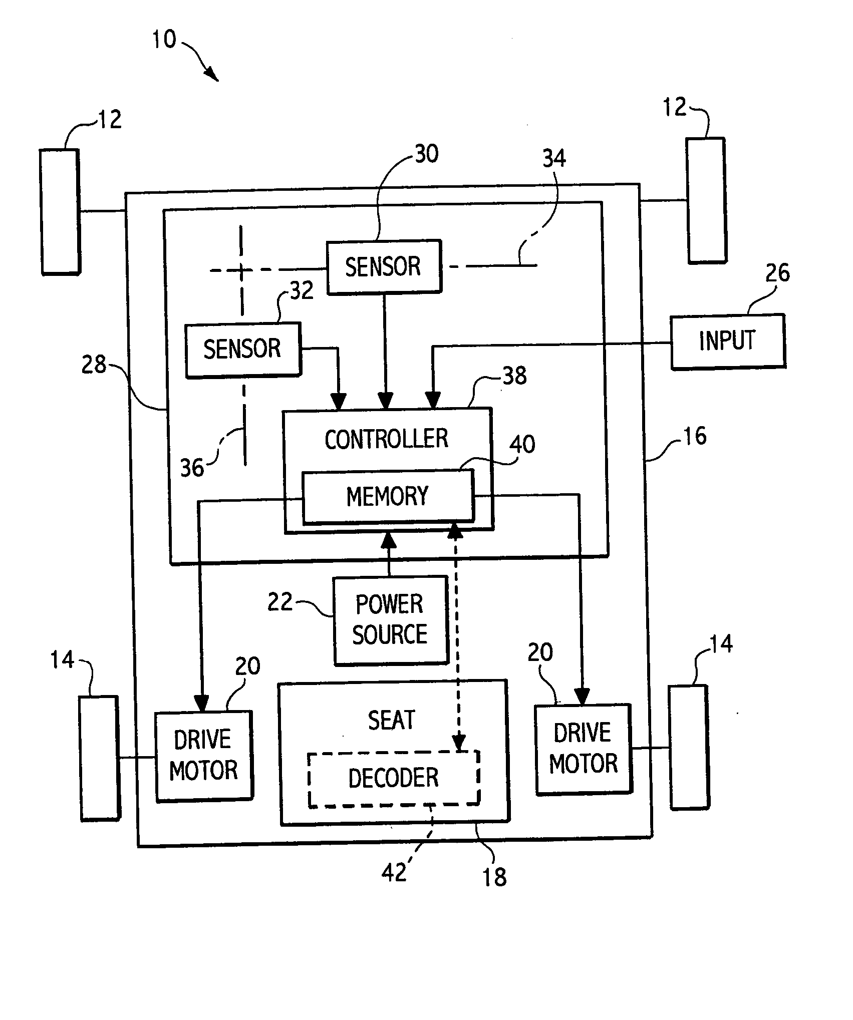
[0016] Referring now to the drawings, there is diagrammatically represented in FIG. 1 a power wheelchair 10 having casters 12 and driven wheels 14 mounted for rotation on a frame 16, which supports a seat 18, preferably an articulating seat, for carrying a wheelchair occupant. The driven wheels 14 are driven by drive motors 20, which are powered by a power source 22, such as a conventional DC battery. The driven wheels 14 may be differentially driven to steer the wheelchair 10. Alternatively, steering motors 24 may be provided for steering the driven wheels 14.

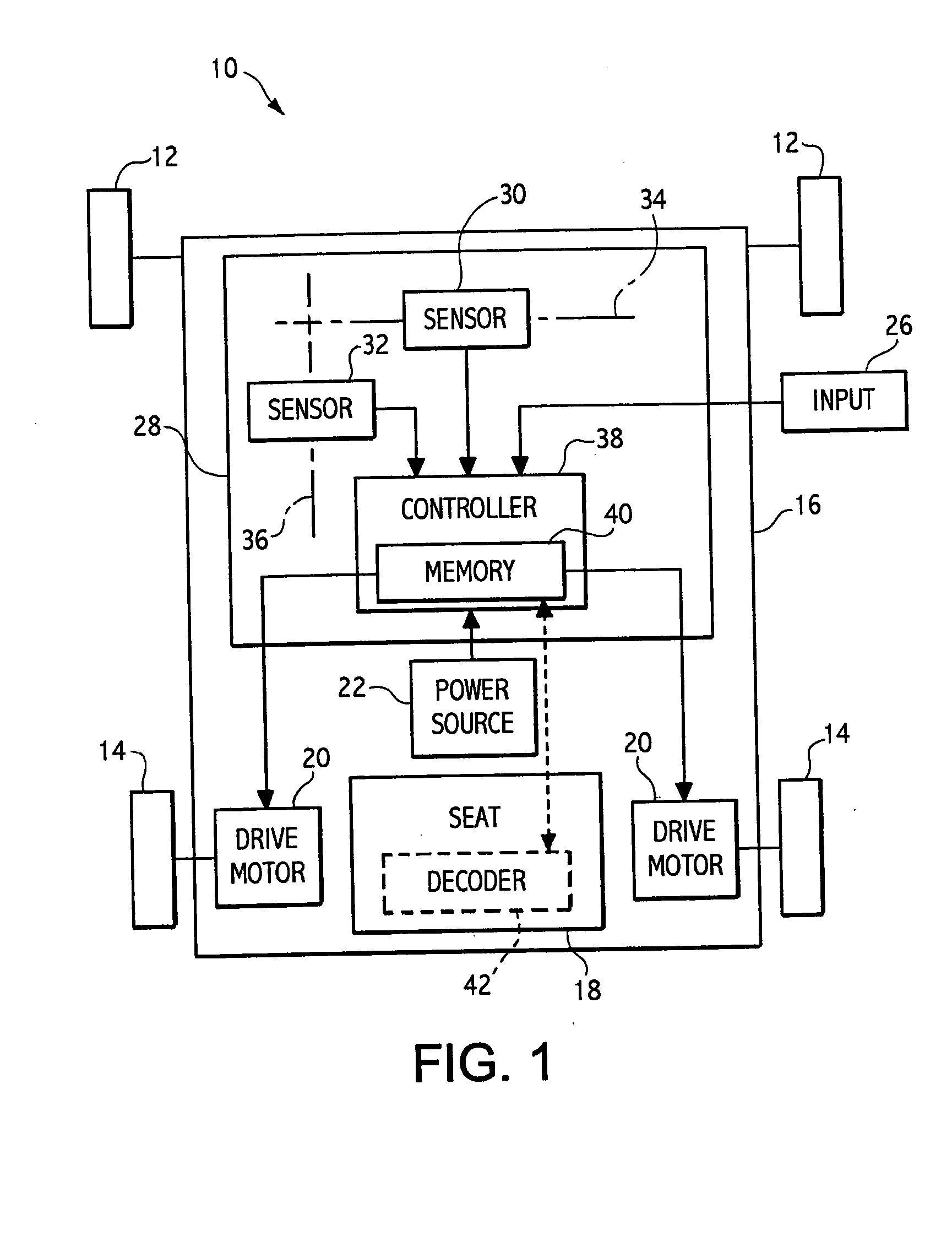
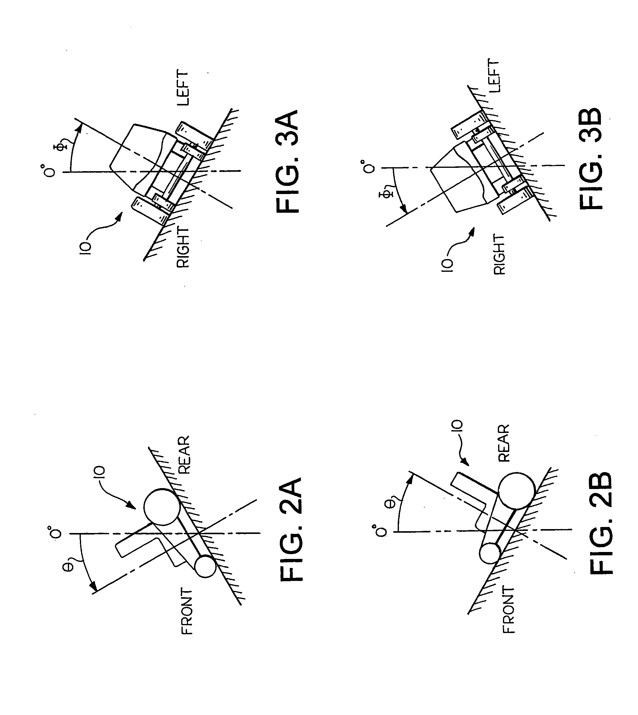
[0017] The operation of the driven wheels 14 depends on input data received from a user via an input device 26. The input device 26 provides an input signal, which corresponds to the input data, to a power wheelchair control system 28. The control system 28 includes one or more on-board devices, such as absolute angle sensors, or tilt and roll sensors, such as the inclinometers 30, 32 shown. The inclinometers 30, 32 are mount...


PUM


Abstract

A power wheelchair incorporates inclinometers to measure angle of pitch and angle of roll. An inclinometer signal is used as an input to a controller. The controller alters drive parameters, such as maximum acceleration, deceleration, and minimum turning radius according to the pitch angle and roll angle of the terrain upon which the wheelchair is operated.

Description

BACKGROUND OF INVENTION [0001] This invention relates in general to motor vehicles and, more particularly, to motorized wheelchairs. Most particularly, this invention relates to a system for controlling the dynamic stability of motorized wheelchairs, wherein drive parameters of the wheelchair are modified based on signals from on-board tilt or roll sensors to insure dynamic stability. [0002] Safe dynamic performance of a wheelchair is considerably influenced by the grade of incline on which the wheelchair is operated. All wheelchairs have a maximum design-safe incline on which the wheelchairs can be operated. These inclines are generally in a range between about 9 degrees and about 14 degrees. Wheelchair control parameters are typically factory set to insure proper stability of the wheelchairs under all “designed-for” terrain conditions (i.e., terrain conditions on which the wheelchair is intended to be operated). Examples of such control parameters include forward and rearward acce...

Claims


Application Information

Patent Timeline
IPC IPC(8): A61GA61G5/04A61G5/10B60K1/00B60K7/00
CPCA61G5/045B60Y2200/84B60K7/0007A61G5/10B60L15/20B60L2200/34B60L2220/46B60L2240/16B60L2240/18B60L2240/20B60L2240/642B60L2260/34Y02T10/64Y02T10/72Y02T90/16
Inventor STEELE, ANGUSTASKER, PETER J.MANSELL, WAYNE T.SCHREIBER, PHILIP
Owner SUNRISE MEDICAL HHC INC
Why Eureka
Try Eureka