Portable charger for mobile phone

Inactive Publication Date: 2005-04-28
R F TECH
View PDF3 Cites 85 Cited by
  • Summary
  • Abstract
  • Description
  • Claims
  • Application Information

AI Technical Summary

Benefits of technology

[0036] In order to accomplish the above object, the present invention provides a portable charger for a mobile phone, including a front housing having an accommodation recess formed in the front side of the front housing to accommodate a mobile phone, and cutouts formed on the right and left sides of the upper portion of the accommodation recess to allow a user to easily grip the mobile phone seated in the accommodation recess and easily manipulate a volume key of the mobile phone; a rear housing fastened to the back of the front housing by screws to close the rear open side of the front housing; a belt clip detachably attached into a long accommodation recess formed on the back of the rear housing to change the mounting position of the rear housing; a fastening unit placed in the long accommodation recess formed on the back of the rear housing to prevent the belt clip from being removed from the accommodation recess; a pair of clamps rotatably placed on the right and left sidewalls of the accommodation recess formed in the front housing to prevent the mobile phone from being removed during charging while engaging with recesses formed on both sides of the mobile phone, respectively; a release button placed above a location between the front housing and the rear housing to regulate protrusion and retraction of projections of the clamps; an interface connector mounted in the lower portion of the accommodation recess, formed in the front housing, through a shaft and a coil spring to be rotated in a block; a secondary battery placed in a space formed by the front and rear housings; and a charge control unit configured to perform control so that Direct Current (DC) voltage, converted by a travel adaptor, is received through a cord and a connector and the second battery and the battery of the mobile phon

Problems solved by technology

Although the conventional portable charger equipped with an internal battery is capable of charging the battery of a mobile phone even at locations where domestic AC power and automobile battery power are not available, the conventional charger is disadvantageous in that the conventional charger is not possible and the charging

Method used


Image

  • Portable charger for mobile phone
  • Portable charger for mobile phone
  • Portable charger for mobile phone

Examples


Embodiment Construction

[0055] Reference now should be made to the drawings, in which the same reference numerals are used throughout the different drawings to designate the same or similar components.

[0056]FIG. 3 is a front view schematically showing a portable charger for a mobile phone according to an embodiment of the present invention. FIG. 4 is a right side view showing the portable charger for a mobile phone with a belt clip in a non-operational position. FIG. 5 is a right side view showing the portable charger for a mobile phone with the belt clip in an operational position. FIG. 6 is a longitudinal section taken along line A-A of FIG. 3 with a secondary battery and a charge control circuit removed therefrom. FIG. 7 is a rearward perspective view showing the portable charger for a mobile phone with the belt clip separated therefrom. FIG. 8 is a rearward perspective view showing the portable charger for a mobile phone with a coupling member is separated from the fastening member of the belt clip. F...


PUM


Abstract

Disclosed herein is a portable charger for a mobile phone. The portable charger includes a front housing, a rear housing, a belt clip, a fastening unit, a pair of clamps, a release button, an interface connector, a secondary battery and a charge control unit. The portable charger is easy to carry, can easily charge the battery of the mobile phone with direct current power charged in a secondary battery, and can simultaneously charge the secondary battery and the battery of the mobile phone using a travel adaptor.

Description

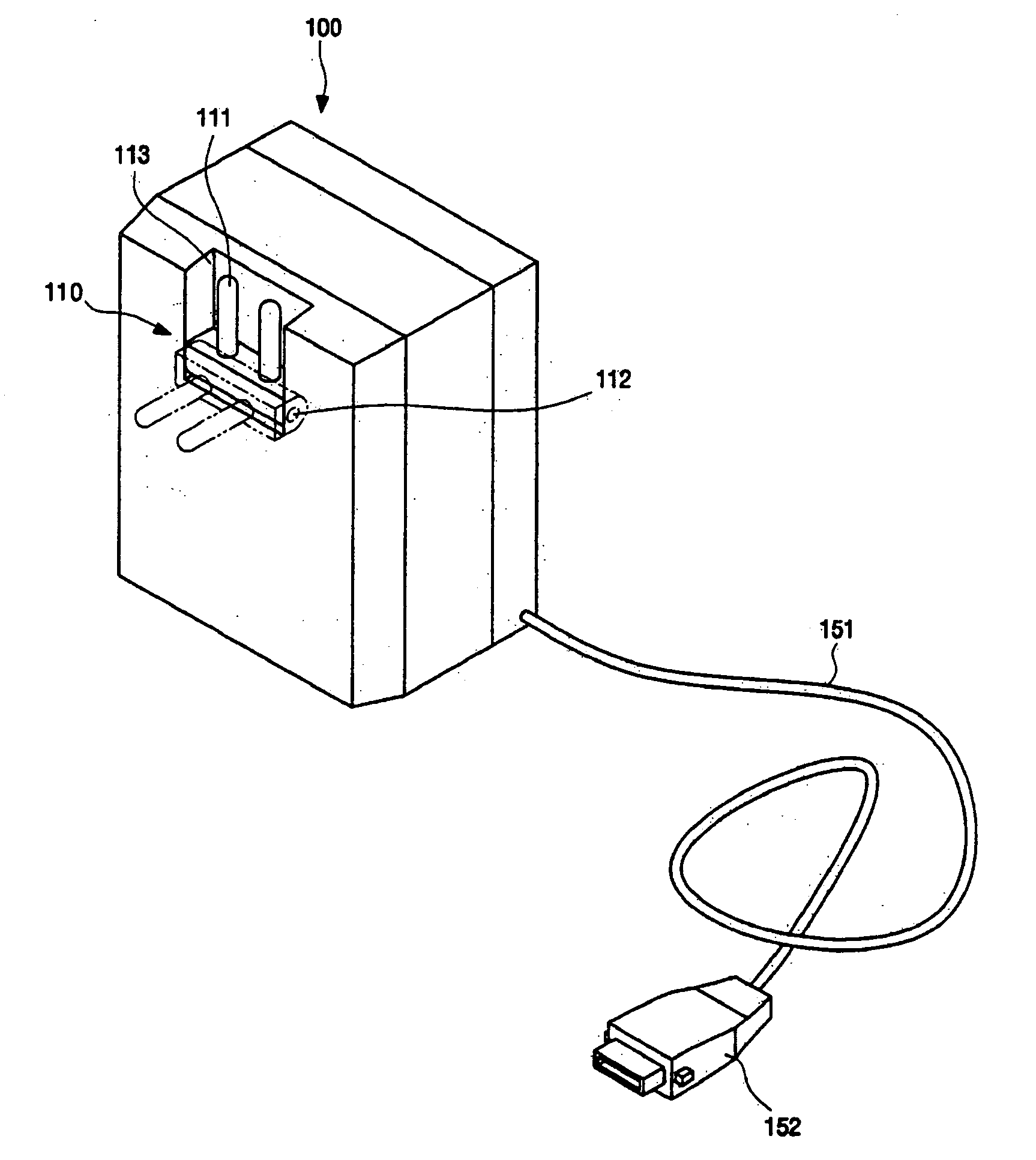
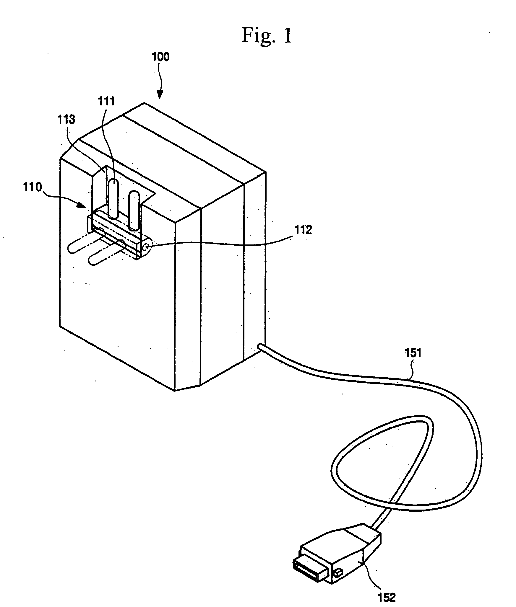
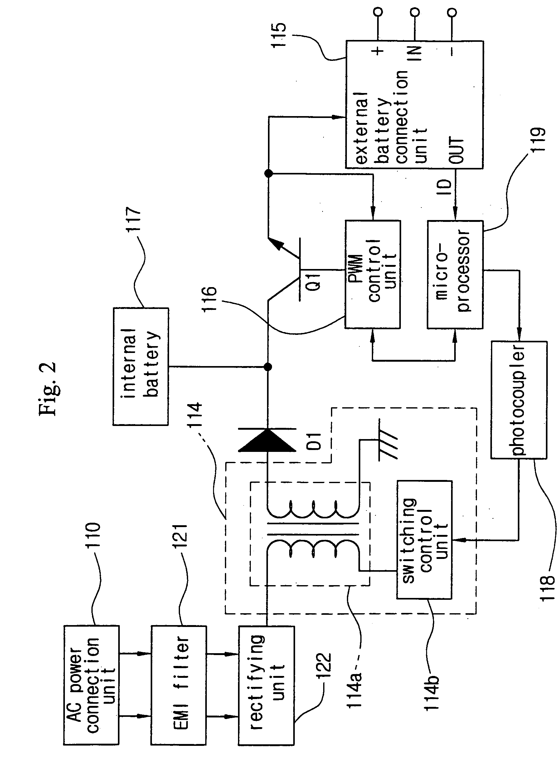
BACKGROUND OF THE INVENTION [0001] 1. Field of the Invention [0002] The present invention relates generally to a portable charger for a mobile phone (also referred to as a mobile communication terminal or a portable phone) and, more particularly, to a portable charger for a mobile phone, which is easy to carry, can easily charge the battery of the mobile phone with direct current power charged in a secondary battery, and can simultaneously charge the secondary battery and the battery of the mobile phone using a travel adaptor. [0003] 2. Description of the Related Art [0004] A conventional portable charger equipped with an internal battery is disclosed in Korean Utility Model Registration No. 20-0275514 (registered on May 1, 2002). [0005] In the portable charger equipped with an internal battery, which is disclosed in Korean Utility Model Registration. No. 20-0275514, an Alternating Current (AC) power connection unit 110 provided with a power plug 111 is attached to a side of a body ...

Claims


Application Information

Patent Timeline
IPC IPC(8): A45F5/00A45F5/02H01M10/42H01M10/46H01M50/202H01M50/244H01M50/247H01M50/262H01M50/296H02J7/00H02J7/02
CPCA45F5/00A45F5/02A45F5/021A45F2005/006A45F2005/025H02J7/02H01M2/1022H01M10/46H02J7/0013H02J7/0044H02J7/0052A45F2200/0516Y02E60/10H01M50/247H01M50/202H01M50/296H01M50/262H01M50/244H02J5/00H02J7/00
Inventor LEE, KYUNG-SANGLEE, JUNG-WOOCHAI, MOON-YOUNG
Owner R F TECH
Why Eureka
Try Eureka